32
Fig. 55
AZX6WSCLOUDDINR
Fig. 56
Fig. 57
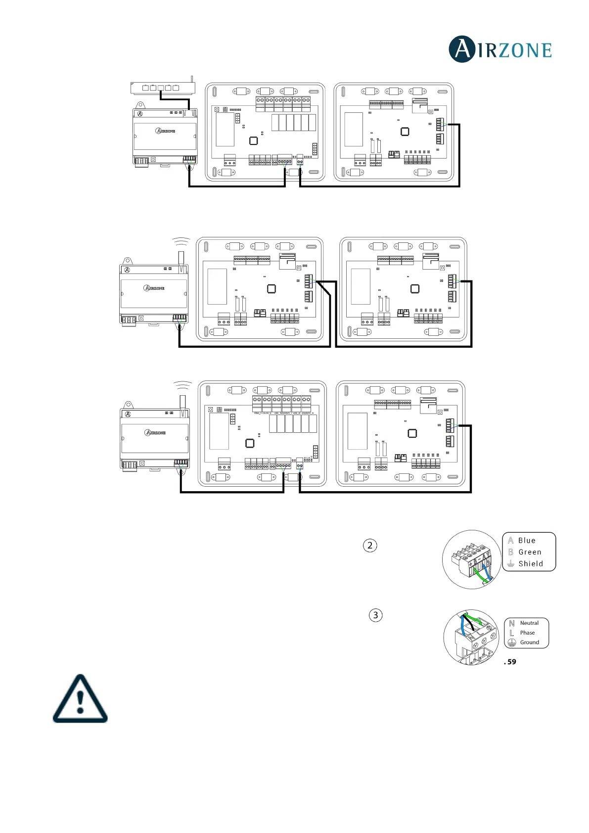
It has a 5-pin terminal to connect to the domotic bus of the Main Control Board . Attach the
wires with the terminal screws following the color code (Fig. 58). Use the shield only on the
connector of the main control board.
The power supply connection to the module is performed with a 3-pin terminal . Attach the
wires with the terminal screws following the color code (Fig. 59).
According to the current local and national regulations, it is mandatory to add a switch (or other element
to disconnect the system) to the external supply wiring so that a constant separation between poles is
guaranteed. The system will restart automatically if the supply is eventually turned off.
independent circuit from the controlled system for the power supply.
 Loading...