ALL-TEST PRO 7™ User Manual
©2019 ALL-TEST Pro, LLC All Rights Reserved 9 Rev 06/20/2019
Instrument Layout
The instrument has three sections:
• Input/output ports
• LED display
• Control Keypad & Function LED’s
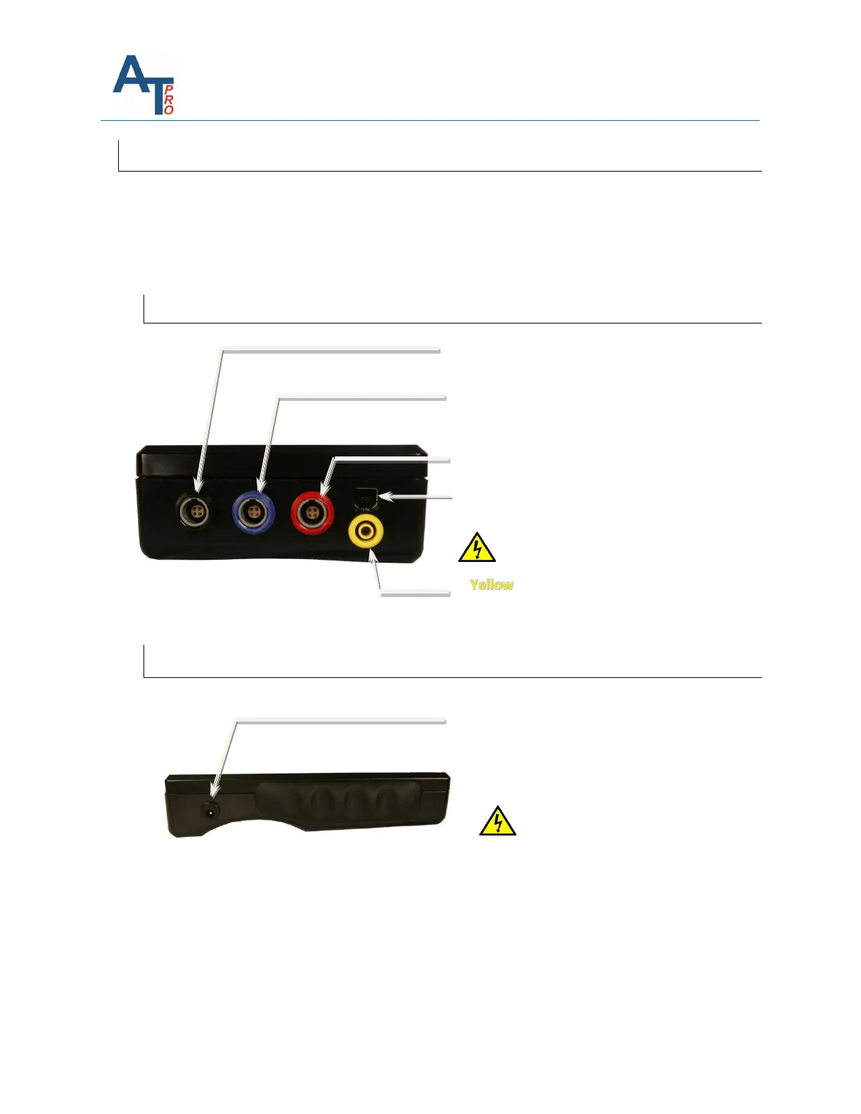
Input/Output Ports
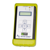
Battery Charging Port
Charger input DC 9V, 1.7A (center pin +
polarity)
USB port (type B) – Communication with PC
RED PORT - Phase 3 Test Lead input/output
port.
BLACK PORT - Phase 1 Black Test Lead port
BLUE PORT - Phase 2 Test Lead port;
Insulation test at 500V & 1000V /
Dissipation Factor and Capacitance test
Port - Return Circuit for Insulation
test /Dissipation Factor and
Capacitance tests
Risk of electric shock!!!
Only use the supplied charger for
charging. Using different charger
could damage your instrument and
void the warranty. It is
recommended to leave the
instrument plugged into charger
when not in use.