©2019 ALL-TEST Pro, LLC All Rights Reserved 25 Rev 06/20/2019
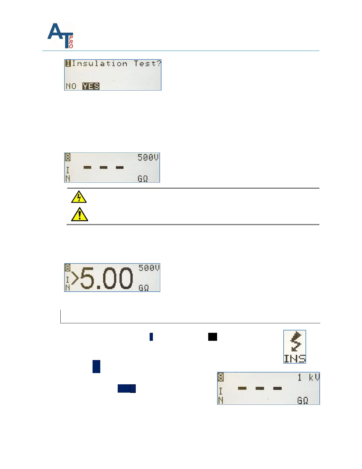
If “YES” is selected “---” will be displayed indicating an empty start value for MΩ.
Select the desired test voltage by pressing the right arrow key, which will toggle between the
two available selections: 500V or 1000V.
NOTE: See Section “INS - Insulation Resistance to Ground (IRG)” for guidelines on performing the
test and interpreting data.
Pressing the TEST key will output the selected test voltage of 500V or 1000V on
the yellow output port and illuminate orange status LED.
To perform Insulation Resistance to Ground (IRG)test:
Press “TEST” key until the GΩ value becomes stable or >5GΩ is displayed, and then OK to
continue.
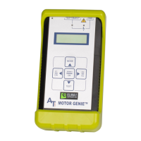
Verifying Proper Ground Connections
1) From the main menu press the ˃ key to highlight the INS function. Connect
Blue Test lead to a ground or earth location, and the Yellow test lead to a
separate ground or earth location.
2) Press the OK key, the screen will display 3 - - -, this
indicates that no measurements have been taken.
3) Press and Hold the TEST ˅key until a value very close
to 0 is displayed. If any other value is displayed one or
the other of the test leads are not properly connected
to ground.