©2019 ALL-TEST Pro, LLC All Rights Reserved 18 Rev 06/20/2019
Electrical Winding Testing Theory
Studies have shown that a leading cause for motor failure is deterioration of the insulation.
There are two different insulation systems. The motor conductors that make up the coils are
individually coated with resin or varnish that acts as insulation to keep the current flowing
through the designed path of the entire winding; this insulation system is called turn or winding
insulation.
The second insulation system is referred to as the ground wall insulation and is located between
the windings and the motor core or stator, this system separates the conductors from the motor
core or frame.
Since current takes the path of least resistance; any weaknesses or faults in the insulation
system will allow flow of the current through the insulations and will allow the current to bypass
or “short circuit” designed flow path. This “short circuiting” will further degrade the operation of
the motor and potentially result in catastrophic failure. Additionally, weaknesses in the ground
wall insulation system will not only degrade motor operation but will lead to increased electrical
shock potential to personnel or plant safety.
Insulation failures can be caused by thermal, electrical, mechanical, and environmental stresses.
Electrical surges, voltage unbalance, incorrect voltage, excessive current or mechanical vibration
are common reasons that cause the insulation to wear and breakdown. Other typical insulation
failures include excessive moisture, contamination, and metallic dust. Some faults are due to
poor manufacturing or assembly of the motor.
Electrical Motor Winding Testing has historically been limited to measuring the DC resistance of
the conductors in Ohms as well as DC resistance of the insulation in Mega-Ohms. These tests are
very common due to the availability of electrical test instruments. The purpose of these
instruments has a multitude functions to make generalized electrical measurements and do
provide some valuable information. In many cases faults that affect these measurements have
been identified.
Hipot tests are designed to look for any weaknesses in the system by applying high voltage and
may result in complete insulation failure by overstressing it. Many of these tests are destructive
and result in a complete failure of the winding as well as additional damage to the stator or
rotor core. Most of these tests are Go - No Go and will only locate existing significant
weaknesses in the insulation system but fail to provide any indication of early degradation of the
insulation system. Therefore, early-stage insulation faults or developing faults that these tests
cannot identify may be present and will damage the motor in a certain period depending on the
deteriorating speed.
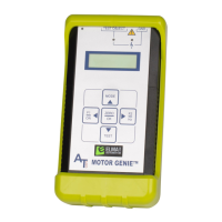
For over 30 years the ALL-TEST PRO® line of motor testers have been the leaders in the industry
in providing easy-to-use handheld instruments specifically designed to test motors. It injects a
series of low voltage signals into the winding system to exercise the effects of the conductors as
well, as the interaction with the insulation system. These instruments allow the technician to