©2019 ALL-TEST Pro, LLC All Rights Reserved 37 Rev 06/20/2019
Rotor Compensated Test
When the parameter of impedance, inductance, phase angle and I/F are in alarm(s), one way to
determine whether the fault comes from stator or rotor is to apply rotor compensated test which
requires an AT7 series instrument. NOTE: If testing an AC induction squirrel-cage rotor motor <1000V
and you have access to turn the motor shaft, perform the DYN test.
1. Performing a rotor compensated winding test.
a. If only a rotor comp test is required select NO for DF/C and INS test.
b. Connect all three test leads when prompted and select “OK”
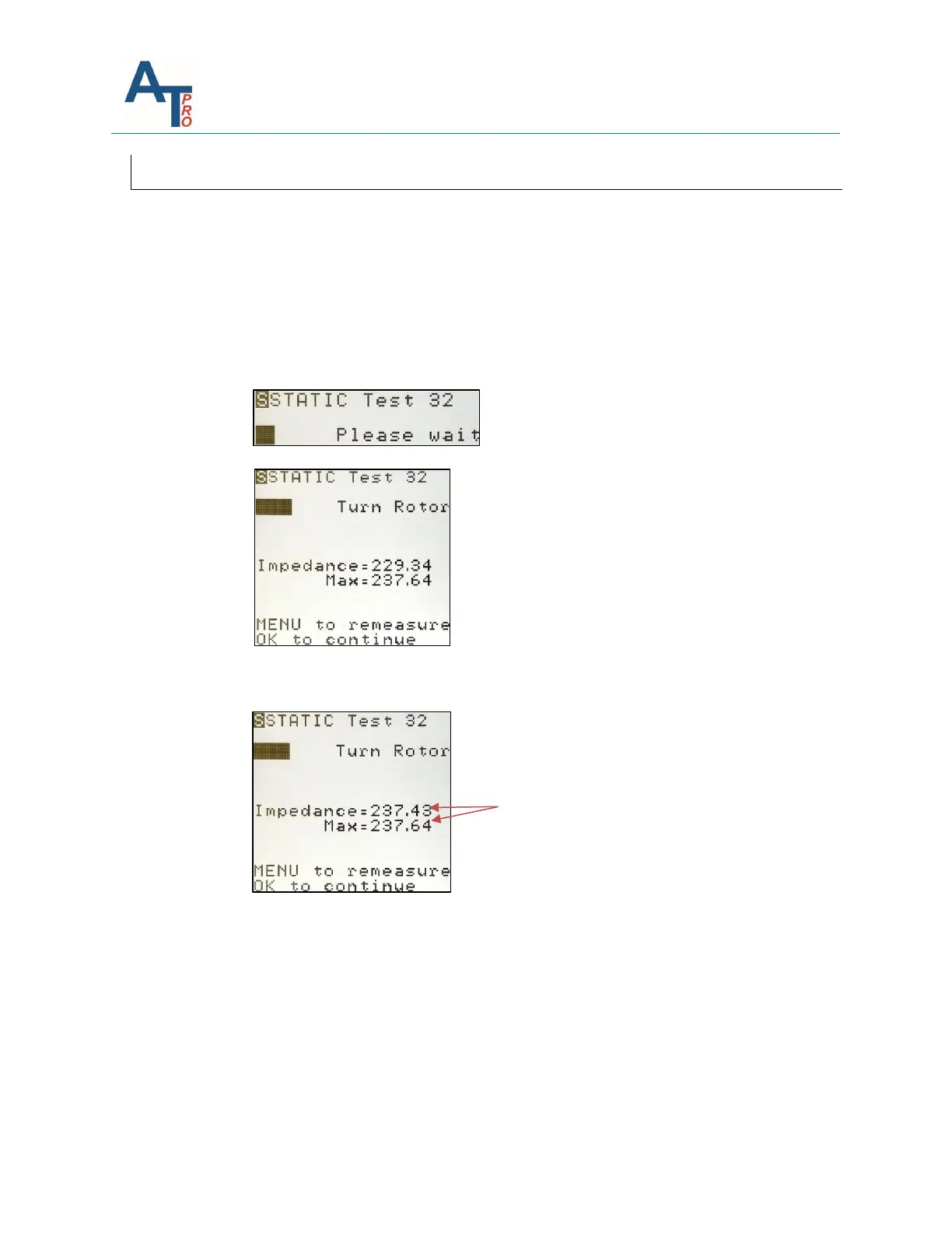
c. A static test between winding 3-2 will automatically begin.
d. The instrument will then display the actual impedance value and MAX.
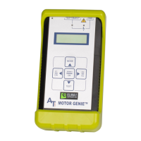
e. Slowly rotate the rotor a minimum of one full revolution. During this rotation the
maximum (MAX) value will automatically display on the instrument screen. Continue
to slowly rotate the motor shaft until the Impedance = maximum value.
e. Press “OK” to continue. The instrument will sequence to winding 2-1.
f. Repeat step d and e for winding 2-1, press OK.
g. Repeat step d and e for winding 3-1, press OK.
2. The rotor compensated test is complete. Save the test results in the same way as
described in Section “Test Save and Reference Comparison”.
f. Run MCA software to upload the test data and perform the 3 Phase AC individual
analysis. If no WARN or BAD alarm shows up on the parameters of impedance,
inductance, phase angle and I/F, it means the motor is in good condition.