Publication 0160-5.18 - June 2003
3-10 Installation and Wiring
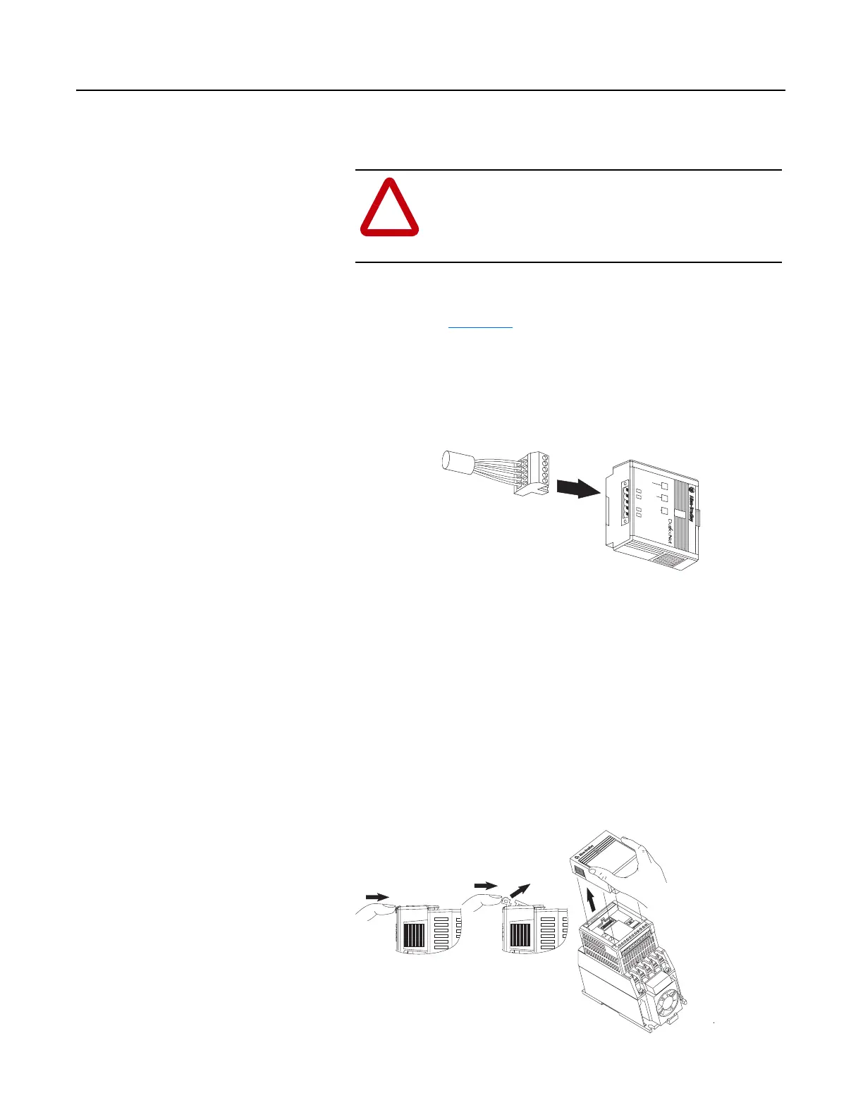
Connecting the DeviceNet Drop
Line to the Module
To connect your module DeviceNet drop line:
1. Turn off the network power supply.
2. Make sure that the DeviceNet 10-pin Linear Plug is correctly
wired (see Figure 3.9
).
3. Locate the DeviceNet connector on the bottom of the module.
4. Insert the plug into the DeviceNet connector.
Figure 3.10
Installing the Drop Line
Removing Communication Module
From a Drive
If you need to reconfigure the Communication Module DIP switches,
you must remove the Communication Module from the drive.
1. Remove the DeviceNet plug from the Communication Module.
2. Press in on the module’s latch and then push away and up.
3. Grasp the module and pull straight up. Avoid bending or twisting
the contact pins located underneath the center portion of the
module.
Figure 3.11
Removing the Communication Module
!
ATTENTION: Do not wire the Communication
Module with the network power supply on. Wiring the
module with the network power supply on may short
your network or disrupt communication.
COMM
FAULT
READY
CONFORMANCE TESTED
TM
1 2 3 4 5 6 7 8 9 10 11
T1
U
T3
W
–
DC
+
DC
T2
V

 Loading...


