Publication 0160-5.18 - June 2003
Troubleshooting 7-3
Understanding the FAULT LED When the FAULT LED is Red, a drive fault is present. To view the
fault code, you must either view P7 - [Present Fault] or read the
value of Class 0x29 (Control Supervisor Object) Instance 1 Attribute
13 (Fault Code).
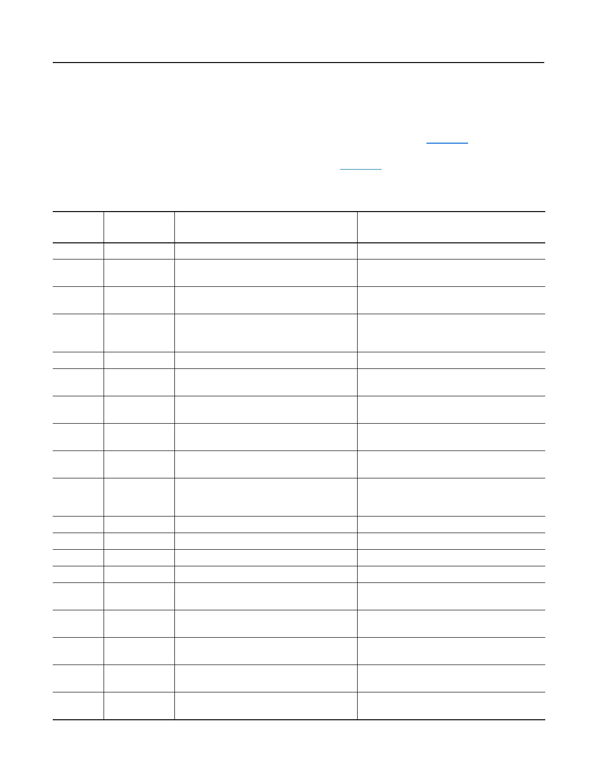
If you view P7 - [Present Fault], refer to Table 7.B
for an
explanation of each fault code. If you read the value of Attribute 13
(Fault Code), refer to Table 7.C
.
Tabl e 7. B Bulletin 160 SSC Interface Fault Codes
Fault Code
Fault
Indication
Description Corrective Action
0 No Fault The drive is currently not faulted. No action required.
3 Power Loss DC Bus voltage remains below 85% nominal on power
up for longer than 5 seconds.
Monitor incoming AC line for low voltage or line power
interruption.
4 Under Voltage DC Bus voltage fell below the minimum value while the
motor was running.
Monitor incoming AC line for low voltage or line power
interruption.
5 Over Voltage DC Bus maximum voltage exceeded. Bus overvoltage caused by motor regeneration. Extend
the decel time, or install dynamic brake option or external
capacitor module. Check for high line voltage.
6 Motor Stalled Motor has stalled. Motor load is excessive. Longer accel time or reduced load required.
7 Motor Overload Internal electronic overload trip. Excessive motor load
exists.
Reduce motor load.
8 Over Temperature Excessive heat detected. Clear blocked or dirty heat sink fins. Check ambient
temperature. Check for blocked or non-operating fan.
11 Operator Fault The keypad has been removed while the drive is
powered or there is excessive noise on the network.
Clear the fault. Do not remove the keypad under power.
Eliminate excessive noise on the network.
12 Over Current Overcurrent detected in hardware trip circuit. Check short circuit at the drive output or excessive load
conditions at the motor.
20 Drive Overload Fault An internal electronic overload trip has occurred. The
drive is over heating.
Clear blocked or dirty heat sink fins. Check ambient
temperature. Check for blocked or non-operating fan.
Reduce motor load current.
22 Drive Reset Stop input not present. Check stop input at TB3 terminal 8.
32 EEPROM Fault EEPROM has invalid data. Reset EEPROM using P56 - [Reset Functions].
33 Max Retries Fault Drive did not reset fault within the max retries specified. Repair system fault.
36 Incompatible Fault Incompatible communication module is installed. Verify compatibility of communication module.
38 Phase U Phase to ground fault detected between drive and motor
phase U.
Check wiring between drive and motor. Check motor for
grounded phase.
39 Phase V Phase to ground fault detected between drive and motor
phase V.
Check wiring between drive and motor. Check motor for
grounded phase.
40 Phase W Phase to ground fault detected between drive and motor
phase W.
Check wiring between drive and motor. Check motor for
grounded phase.
41 UV Short Excessive current has been detected between these
two drive output terminals.
Check the motor and external wiring to the drive output
terminals for a shorted condition.
42 UW Short Excessive current has been detected between these
two drive output terminals.
Check the motor and external wiring to the drive output
terminals for a shorted condition.

 Loading...


