EasyManuals Logo
Home>Allen-Bradley>Control Unit>160-DN2

Allen-Bradley 160-DN2 User Manual

Allen-Bradley 160-DN2
116 pages
To Next Page IconTo Next Page
To Previous Page IconTo Previous Page
Page #14 background imageLoading...
Page #14 background image
Publication 0160-5.18 - June 2003
1-2 Product Overview
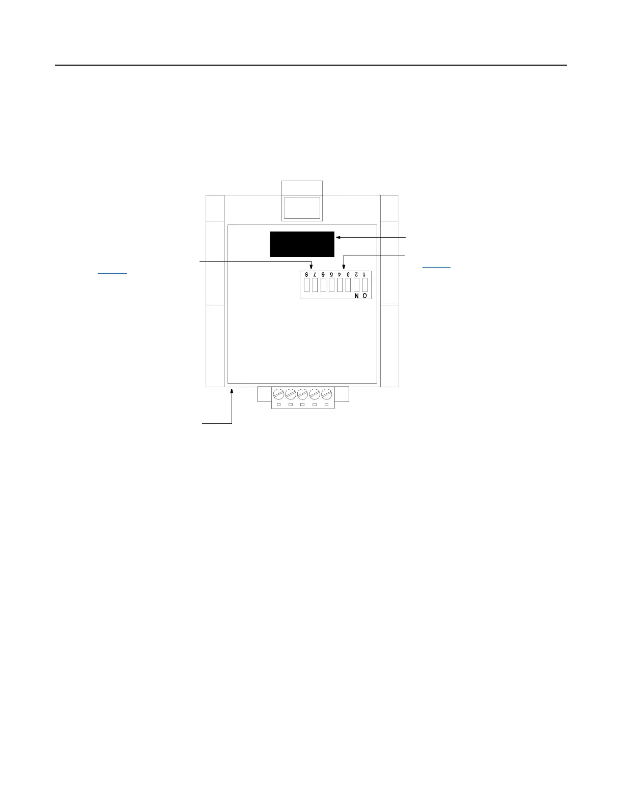
DIP Switches Figure 1.2
Module Rear View
The Communication Module has one eight position DIP switch for setting the
DeviceNet Node Address and Baud Rate. DIP switches are located on the
rear of the module and are only accessible when the module is removed
from the Bulletin 160 SSC drive.
SW.1 - SW.6 = Node Address Selection
(see page 3-6
)
Expansion/Keypad Port Connector
SW.7 - SW.8 = Baud Rate Selection
(see page 3-7
)
Label with DeviceNet Serial Number

Table of Contents

Questions and Answers:

Question and Answer IconNeed help?

Do you have a question about the Allen-Bradley 160-DN2 and is the answer not in the manual?

Allen-Bradley 160-DN2 Specifications

General IconGeneral
BrandAllen-Bradley
Model160-DN2
CategoryControl Unit
LanguageEnglish

Related product manuals