Publication 0160-5.18 - June 2003
Installation and Wiring 3-9
Wiring the DeviceNet Connector Follow these recommendations for communications wiring:
•See DeviceNet Cable System Planning and Installation Manual,
Publication DN-6.7.2, for planning and installing DeviceNet
networks.
• Keep communication wiring away from high noise sources such as
motor cables.
• Increase noise immunity by:
– Using a trunk line in place of a drop line.
– Using a ferrite cable clamp around the communication line
(see Figure 3.9
).
– Grounding the cable shield as shown in Figure 3.9
.
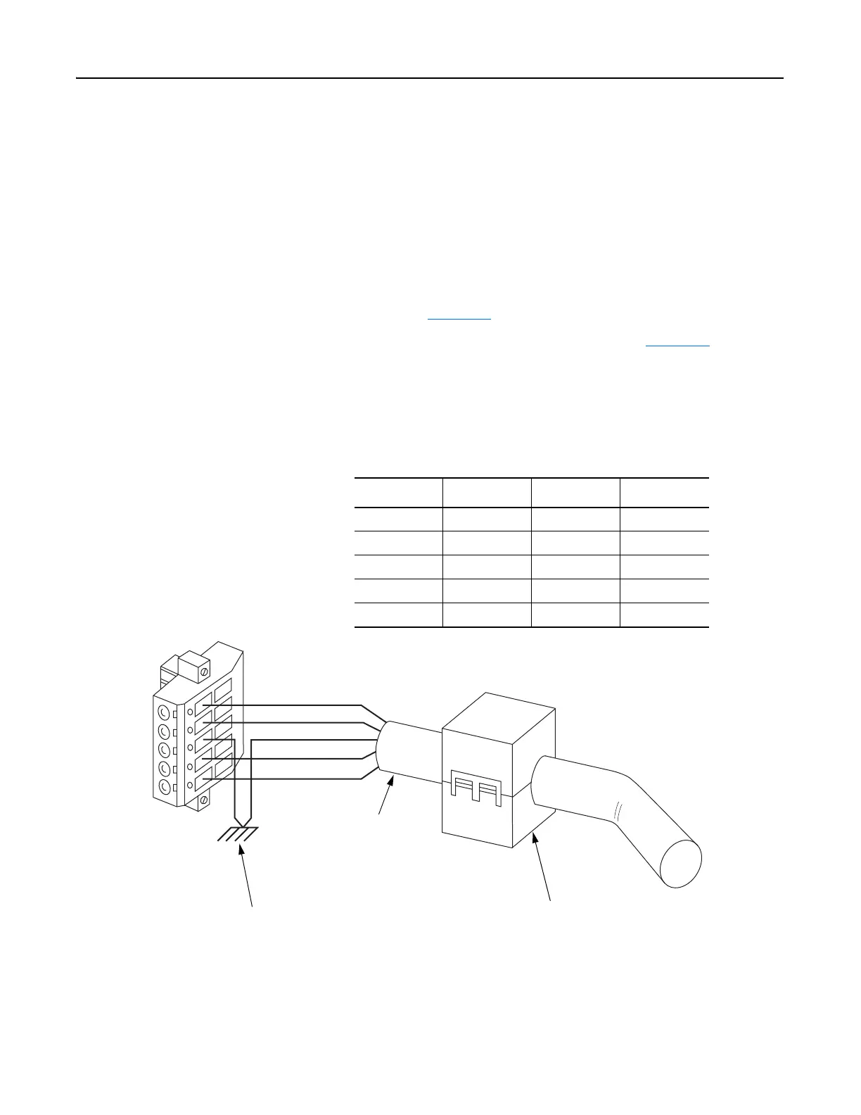
Figure 3.9
Wiring the DeviceNet 10-Pin Linear Plug
1 2 3 4 5
Red
White
Bare
Blue
Black
The Communication Module receives power and communications through the DeviceNet connector.
DeviceNet cable wires connect to the DeviceNet plug as shown below:
Color Terminal Signal Function
Black 1 COMM Common
Blue 2 CAN_L Signal Low
Bare 3 SHIELD Shield
White 4 CAN_H Signal High
Red 5 VDC+ Power Supply
DeviceNet Trunk Line
or Drop Line
Trunk line is recommended for
greatest noise immunity.
Grounding Recommendations
Attach bare wire to earth GND as close to the drive as
possible. For greatest noise immunity, drive should be
single point ground.
Important: For each DeviceNet Network with multiple
devices, only one device must be grounded.
Optional Clamp-On Ferrite Cable Clamp
Install core within 10 cm (4") of Communication
Module. Use Ferrishield (part #HI28B2039) or
Fair-Rite (part #0443164151 – quantity of 2 required).

 Loading...


