Publication 0160-5.18 - June 2003
Using 160-DN2 with DeviceNet Scanner 6-19
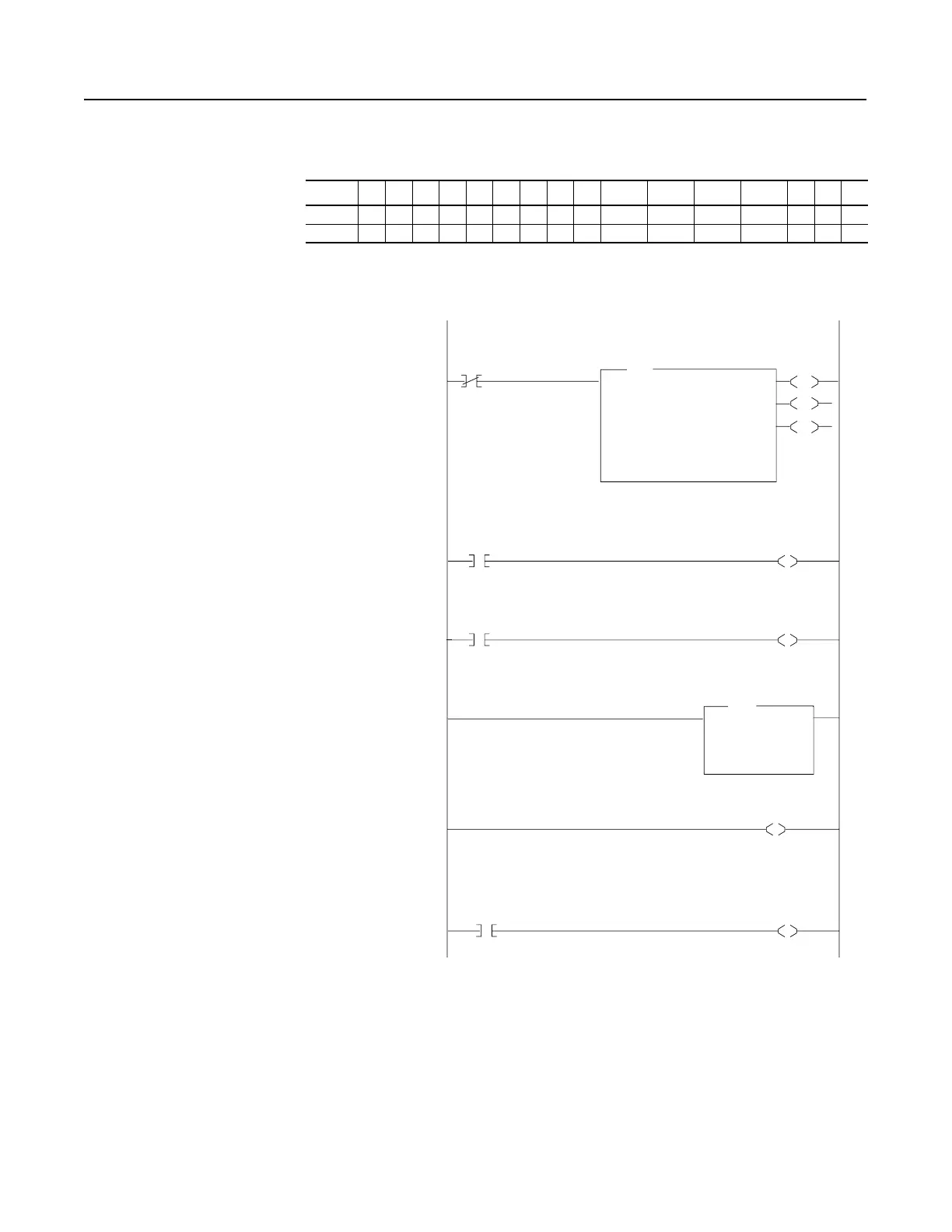
Using I/O Messaging (Continued) PLC-5 Example
Figure 6.15
Example PLC-5 Ladder Logic Program
Table 6.D Control File for Block Transfer
EN ST DN ER CO EW NR TO RW RLEN DLEN FILE ELEM R G S
BT20:0000000000620900000
BT20:100000000062 0 10 0 0000
0000
BT20:0
EN
EN
DN
ER
BTR
Block Transfer Read
Module Type Generic Block Transfer
Rack 000
Group 0
Module 0
Control Block BT20:0
Data File N9:0
Length 62
Continuous No
0001
N9:1
1
Bulletin 160
RUNNING
Status Bit
O:000
10
Operator Display
Drive Running
Status Bit
0002
N9:1
7
Bulletin 160
FAULTED
Status Bit
O:000
11
Operator Display
Drive Faulted
Status Bit
0003
MO
Move
Source N9:2
0<
Dest N21:1
0<
MOV
Operator Display
Drive Feedback
Status Word
0004
N10:0
0
1771-SDN Scanner
Port A Enable
0005
I:000
10
Operator Input
Drive Start
Command Bit
N10:1
1
Bulletin 160
START
Command Bit
The scanner gathers drive status data via the DeviceNet network. The Block Transfer Read
in this rung then moves the drive status data from the scanner to the N9 data file in the PLC.
These rungs move the drive status from the Block
Transfer Read data file to an operator display.
This rung enables the scanner.
These rungs move the inputs of the operator from
the operator station to the Block Transfer Write
data file. They will then be sent to the scanner
and out to the drive via the DeviceNet network.

 Loading...


