Publication 2707-UM005B-EN-P
Microview Overview 2-5
MODE Key Operations
The MODE key accesses a menu of options allowing you to set
features and operating parameters of the MicroView.
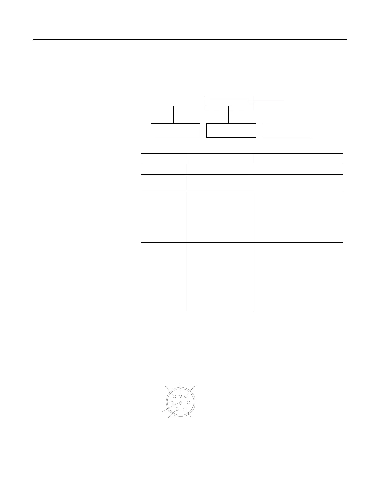
Communications Port
All communications are through an 8 pin mini DIN connector on the
top of the MicroView. The connector is an RS-232 port.
MicroView Communications Port
1 Code
2 Scal
3 Sim
4 Test
1 P-A/D
2 Mode
3 Prgm
4 Clr Fit
5 Ex
Baud Rate
1 Reset
2 Comm
3 Spec
4 Other
Mode Menu Select this option: To perform this function:
1 Reset Resets the Unit
2 Comm
1 Baud Rate Specifies 300, 1200, 2400, 9600, 19200
bits per second
3 Special
1 P-A/D
2 Mode
3 Prgrm (Program)
4 Clr Flt (Clear Fault)
Displays and/or modifies data files in the
processor.
Places processor in RUN mode or
PROGRAM mode. Transfers application
files between the MicroView and PC.
Clears all processor faults in the
MicroLogix controller.
4 Other
1 Code
2 Scal (Scale)
3 Sim (Simulate)
4 Test
5 Ex (Exit)
Modifies the master security code of the
MicroView.
Converts controller values to engineering
units.
Verifies an application without controller
connected.
Tests memory, communications, keyboard
and display.
Returns to the Mode menu.
1
2
3
6
7
8
5
4
Pin #
1
2
3
4
5
6
7
8
Mounting
Signal Name
+24V dc from MicroLogix
VDC Common
Cable Shield
Receive Data (RXD)
Not Used
Not Used
Transmit Data (TXD)
Signal Ground
Cable Shield
 Loading...