EasyManuals Logo

Allen-Bradley 2707-MVP232 User Manual

Allen-Bradley 2707-MVP232
92 pages
To Next Page IconTo Next Page
To Previous Page IconTo Previous Page
Page #48 background imageLoading...
Page #48 background image
Publication 2707-UM005B-EN-P - July 2000
6-4 Installing the MicroView Operator Interface
4. Alternately tighten the mounting nuts until the terminal is held
firmly against the panel. Tighten mounting nuts to a torque of
10 inch-pounds. Do not over-tighten nuts.
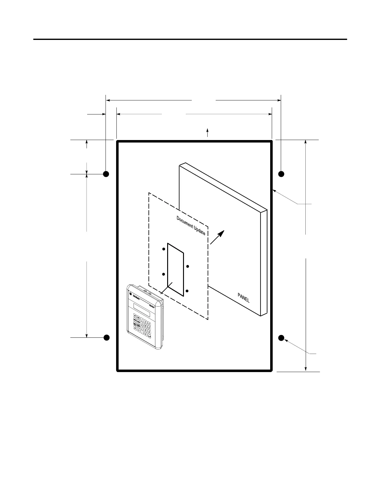
3.888 in.
(98.8 mm)
3.490 in.
(88.6 mm)
0.199 in.
(5.05 mm)
0.760 in.
(19 mm)
3.660 in.
(93.0 mm)
5.180 in.
(131.0 mm)
Cutout Must
Not Exceed
Outside of line
0.172 in.
(4.37 mm)
TOP - FRONT
Make sure cutout is positioned with TOP - FRONT visible on the
front of the panel before marking.

Table of Contents

Questions and Answers:

Question and Answer IconNeed help?

Do you have a question about the Allen-Bradley 2707-MVP232 and is the answer not in the manual?

Allen-Bradley 2707-MVP232 Specifications

General IconGeneral
BrandAllen-Bradley
Model2707-MVP232
CategoryRecording Equipment
LanguageEnglish

Related product manuals