1761-6.5
5-24
DNI Configuration Parameters and Programming Notes
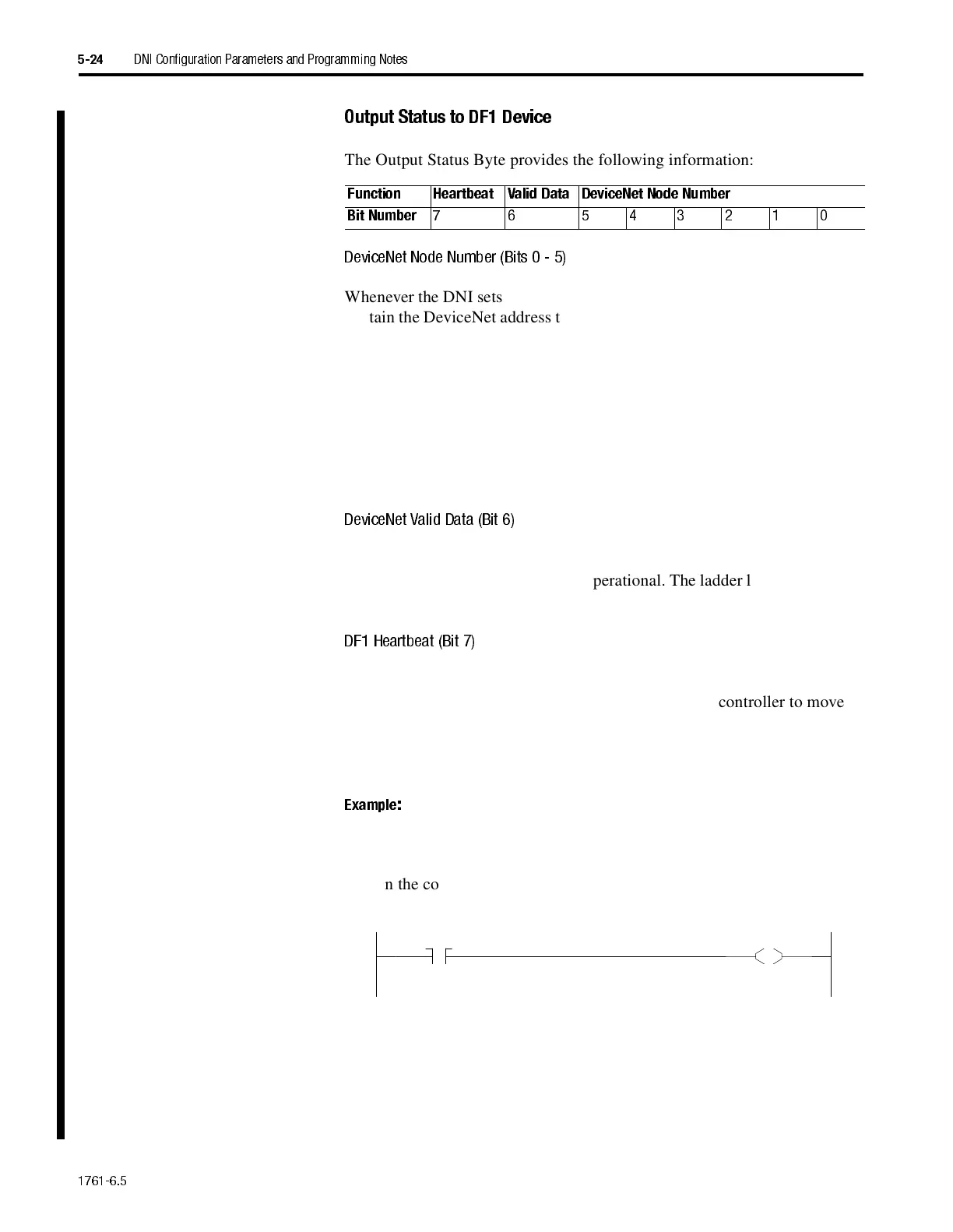
Output Status to DF1 Device
The Output Status Byte provides the following information:
DeviceNet Node Numb er (Bits0-5)
Whenever the DNI sets (writes) output data to the DF1 device, these six bits
contain the DeviceNet address that the DNI is assigned on DeviceNet. If the
user program needs to know what node number its DNI is configured for,
program a masked move (MVM) instruction in the ladder logic to move the
node number out of this byte. The MVM should have:
•
its destination address located in the controller’s integer file
•
a masked value of 003F
•
the source address should match the location identified by the Output
Word Offset parameter.
DeviceNet Vali d Data (Bit 6)
The DNI sets this bit (1) to the DF1 device whenever it detects that the
DNI’s DeviceNet master is on-line/operational. The ladder logic program in
the controller should monitor this bit and take any necessary control action.
DF1 Heartbeat (Bit 7)
The DNI writes the status of this bit to the controller, using the interval set
by the DF1 Heartbeat parameter. The DNI expects the controller to move
the status of bit 7 from the output data area to the input data area. The
easiest way to accomplish this is by programming an XIC instruction in
series with an OTE instruction as shown in the following example.
Example
:
With the starting output word at N7:95 (Output Word Offset), and the
starting input word at N7:90 (Input Word Offset), you need to program this
rung in the controller’s program to move the heartbeat bit.
Your program should also monitor N7:95/7 for activity. If activity is lost, it
represents a problem with the connection to the DNI, or the DNI has some
type of error or problem.
See the application example "MicroLogix as I/O on DeviceNet" on page 7-1
for more information about using the DF1 Heartbeat.
Function Heartbeat Valid Data DeviceNet Node Number
Bit Number
7 6 543210
N7:95
7
N7:90
7
 Loading...