Rockwell Automation Publication IASIMP-QS035B-EN-P - April 2015 21
Prepare the Kinetix 5500 Drive Hardware Chapter 1
Wiring Guidelines
Follow these steps when wiring the connectors for your Kinetix 5500 drive.
1. Prepare the wires for attachment to each connector plug by removing insulation equal to the recommended strip
le
ngth.
2. Route the cable/wires to your Kinetix 5500 drive.
See the interconnect wiring diagram on page
20 for connector pinouts.
3. Insert wires into connector plugs.
4. Tighten the connector screws.
5. Gently pull on each wire to make sure that it does not come out of its terminal; reinsert and tighten any loose wires.
6. Insert the connector plug into the drive connector.
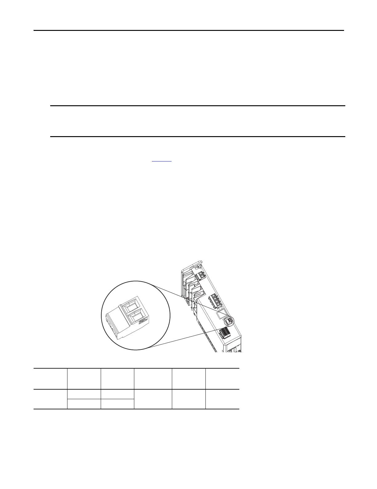
Wire the 24V Control Power Input Connector
The 24V power (CP) connector requires 24V DC input for the control circuitry.
Table 3 - 24V Power (CP) Connector Specifications
When you remove insulation from wires and tighten screws to secure the wires, refer to the tables provided for strip
lengths and torque values.
Use caution not to nick, cut, or otherwise damage strands as you remove the insulation.
24V-
24V+
1
2
Remove
For DC
Bus Only
Kinetix 5500 Drive
Top View
24V (CP) Connector Plug
Drive Cat. No. CP Pin Signal Recommended
Wire Size
mm
2
(AWG)
Strip Length
mm (in.)
Torque Value
N•m (lb•in)
2198-Hxxxx-ERS CP-1 24V+ 2.5…0.5
(14…20)
7.0 (0.28) 0.22…0.25
(1.9…2.2)
CP-2 24V-

 Loading...


