Rockwell Automation Publication IASIMP-QS035B-EN-P - April 2015 43
Add a Kinetix 5500 Drive to a Logix Designer Application Chapter 1
Test and Tune the Axis
For help using the Logix Designer application as it applies to testing and tuning your axes with ControlLogix® EtherNet/IP
modules or CompactLogix 5370 controllers, refer to Additional Resources on page
9.
Test the Axes
Follow these steps to test the axes.
1. Verify that the load was removed from each axis.
2. In your Motion Group folder, right-click an axis and choose Properties.
The Axis Properties dialog box opens.
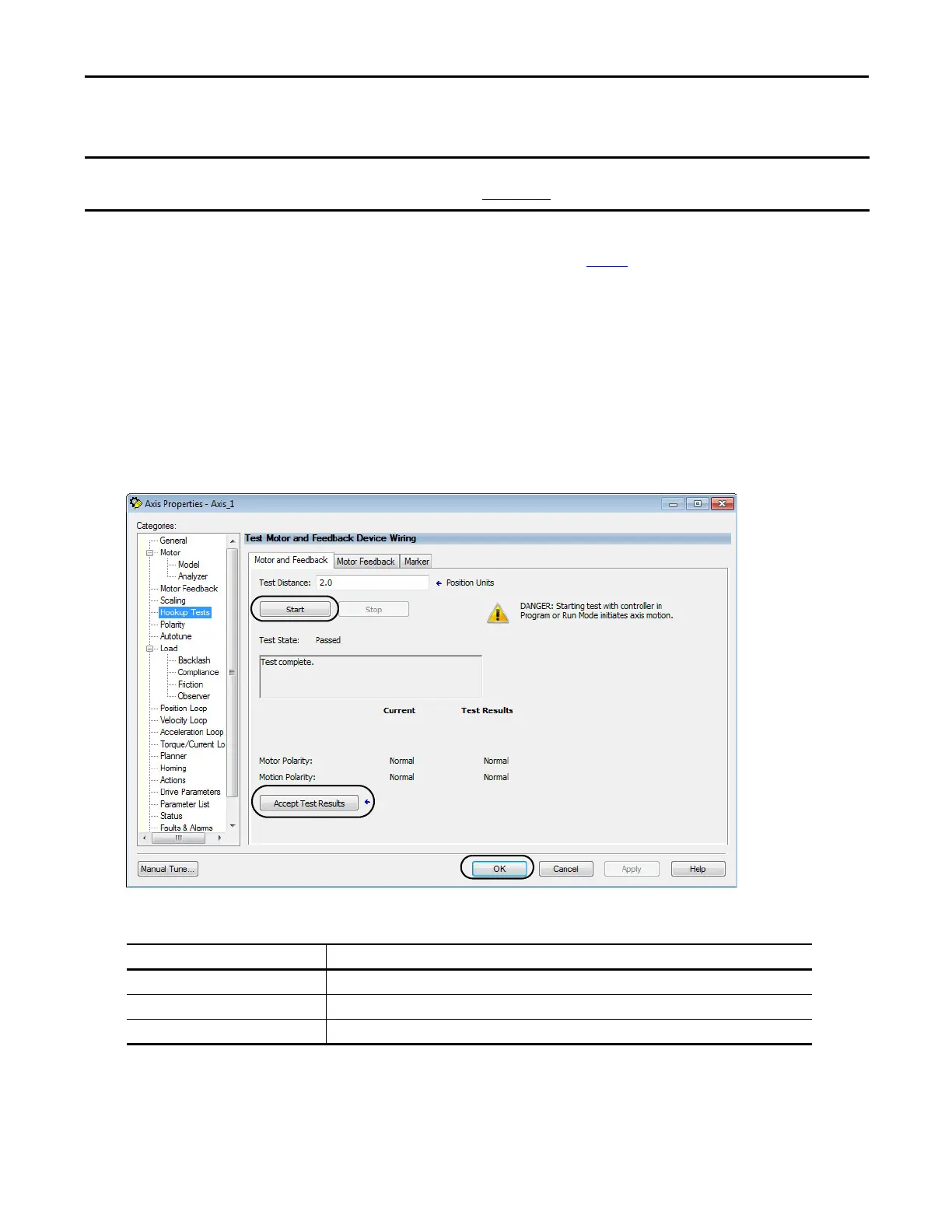
3. Click the Hookup Tests category.
4. In the Test Distance field, type 2.0 as the number of revolutions for the test.
5. Click the desired tab (Marker/Motor Feedback/Motor and Feedback).
In this example, the Motor and Feedback test is chosen.
6. Click Start.
Before proceeding with testing and tuning your axes, verify that the MOD and NET status indicators are operating as described in
the Kinetix 5500 Servo Drives User Manual, publication
2198-UM001.
Test Description
Marker Verifies marker detection capabilit
y as you rotate the motor shaft.
Motor Feedback Verifies that feedback connections are wired corr
ectly as you rotate the motor shaft.
Motor and Feedback Verifies that motor power and feedback connections are wired correctly as you command the motor to rotate.
 Loading...


