24 Rockwell Automation Publication IASIMP-QS035B-EN-P - April 2015
Chapter 1 Prepare the Kinetix 5500 Drive Hardware
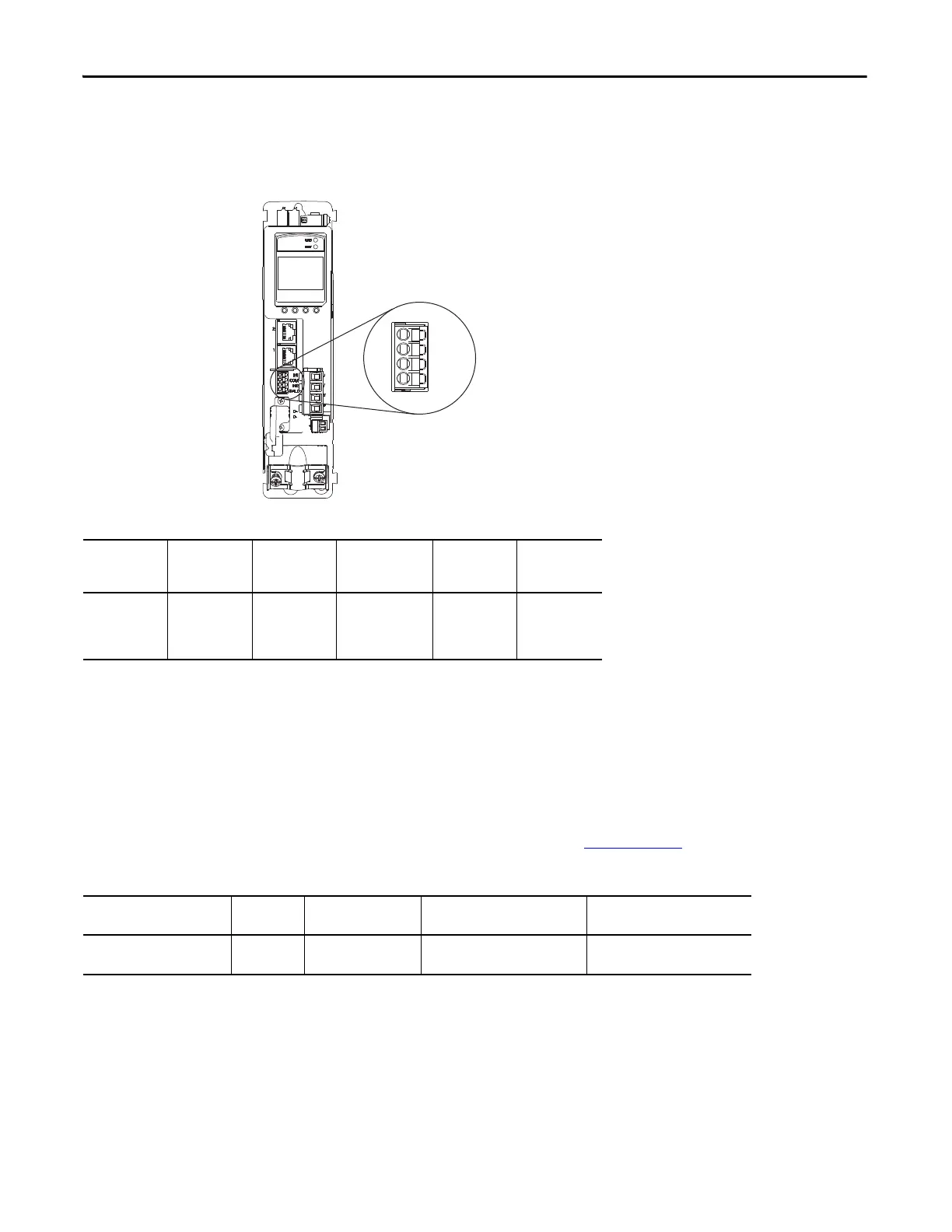
Wire the Digital Inputs Connector
The digital inputs (IOD) connector uses spring tension to hold wires in place.
Table 6 - Digital Inputs (IOD) Connector Specifications
Wire the Motor Power, Brake, and Feedback Connectors
The Kinetix 5500 drives use one cable that includes conductors for motor power, brake, and encoder feedback. Bulletin
2090 cables are available with and without the motor brake conductors.
See the Kinetix Motion Accessories Specifications Technical Data, publication
GMC-TD004, for cable specifications.
Table 7 - Single Cable Catalog Numbers
Digital Inputs (IOD) Connector Plug
Kinetix 5500 Servo Drive
(front view)
Drive Cat. No. DC Pin Signal Recommended
Wire Size
mm
2
(AWG)
Strip Length
mm (in.)
Torque Value
N•m (lb•in)
2198-Hxxxx-ERS IOD-1
IOD-2
IOD-3
IOD-4
IN1
(1)
COM
IN2
SHLD
(1) This signal has dual-functionality. You can use IN1 (IOD-1) as registration or Home input.
1.5…0.2
(16…24)
10.0 (0.39) N/A
Motor Connector
Ty
pe
Motor Cat. No. Motor Cable Cat. No.
(with brake wires)
Motor Cable Cat. No.
(without brake wires)
Kinetix VP (Bulletin VPL) Circular DIN
(SpeedTec)
VPL-A/Bxxxxx 2090-CSBM1DF-xxAAxx
(standard) cable
2090-CSWM1DF-xxAAxx
(standard) cable

 Loading...


