28 Rockwell Automation Publication IASIMP-QS035B-EN-P - April 2015
Chapter 1 Prepare the Kinetix 5500 Drive Hardware
Apply the Single Motor Cable Shield Clamp
Factory-supplied 2090-Series single motor cables are shielded, and the braided cable shield must end at the drive during
installation. A small portion of the cable jacket has been removed to expose the shield braid. The exposed area must be
clamped (with the clamp provided) at the bottom front of the drive.
This procedure assumes that you have completed wiring your motor power, brake, and feedback connectors and are ready
t
o apply the cable shield clamp.
Follow these steps to apply the motor cable shield clamp.
1. Loosen the clamp screws and remove at least one of the screws.
SHOCK HAZARD: To avoid hazard of electrical shock, make sure that shielded power cables are grounded according to
recommendations.
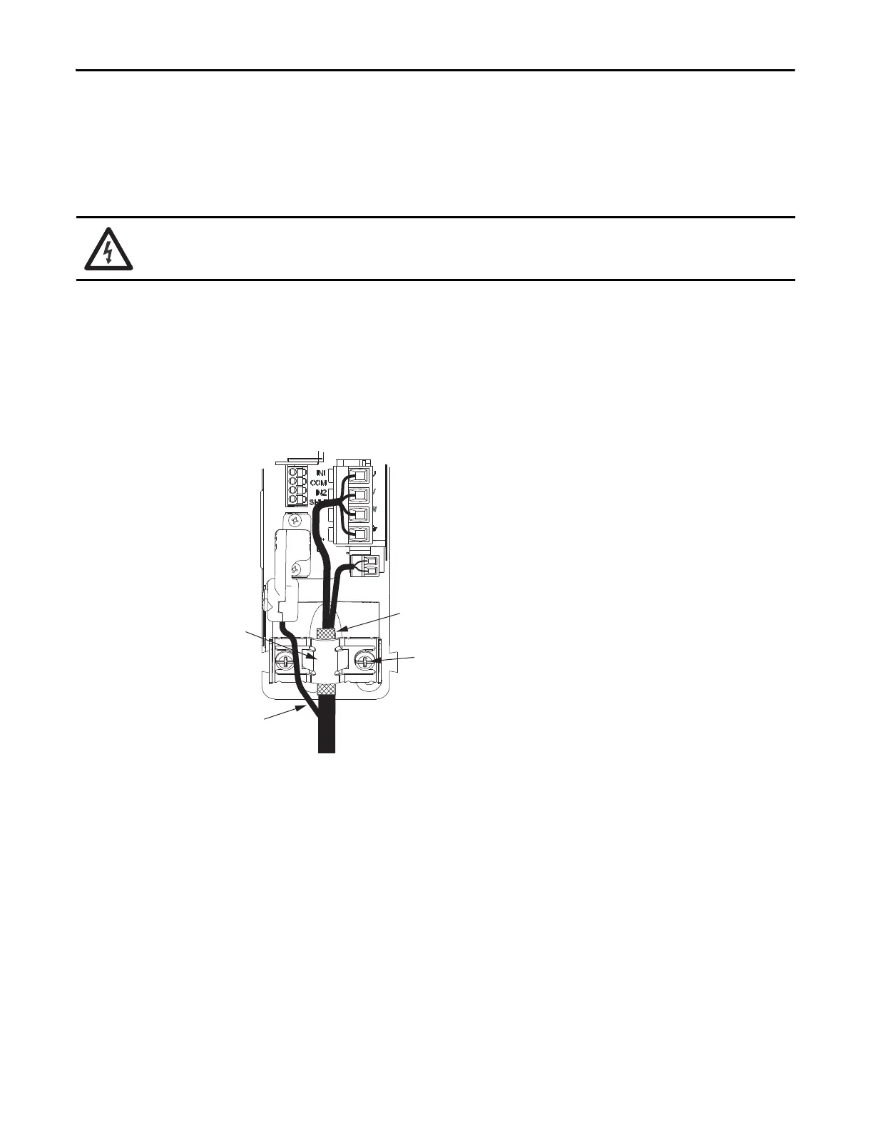
Motor Cable
Shield Clamp
2198-KITCON-DSL
Motor Feedback
Connector Kit
Motor Power
(MP) Connector
Motor Brake
(BC) Connector
Exposed shield braid
under clamp.
Cable clamp screws
tightened.
Kinetix 5500 Servo Drives
(frame 1) Front View
2090-CSBM1DF-18AAxx
Motor Cable
Feedback cable routed
around the shield clamp.
Figure 5 - 18 AWG Cable Installation
When the drive/motor combination calls for 18 AWG cable, the feedback cable routes around the motor cable shield clamp.

 Loading...


