Rockwell Automation Publication IASIMP-QS035B-EN-P - April 2015 27
Prepare the Kinetix 5500 Drive Hardware Chapter 1
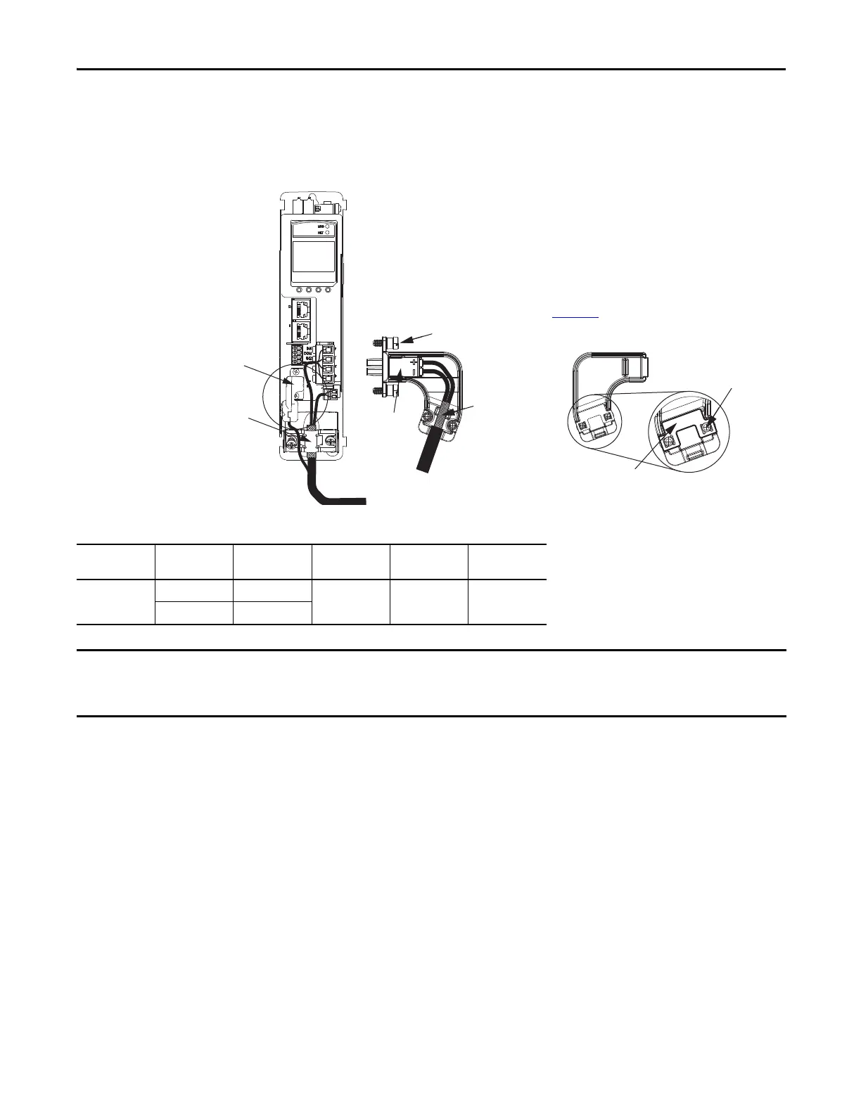
Motor Feedback Connections
Feedback connections are made by using the 2090-KITCON-DSL feedback connector kit, which is included with your
Kinetix 5500 drive.
Table 10 - Motor Feedback (MF) Connector Specifications
Drive Cat. No. Pin Signal/
Wire Color
Wire Size
AWG
Strip Length
mm (in.)
Torque Value
N•m (lb•in)
2198-Hxxx-ERS MF-1 D+/Blue 22 8.0 (0.31) 0.4 (3.5)
MF-2 D-/White
Motor Cable
Shield Clamp
Motor Feedback
Connector Kit
2198-KITCON-DSL
Feedback Connector Kit
Connector
Housing
See the Kinetix 5500 Feedback Connector
Kit Installation Instructions, publication
2198-IN002
, for connector kit specifications.
Internal
Grounding Plate
Clamp Screws (2)
Mounting Screws (2)
Exposed Shield
Feedback Cable
(EPWR+, EPWR-)
Cover
Kinetix 5500 Servo Drive
(front view)
2090-CSxM1DF-18AAxx
Motor Cable
The feedback bundle in 2090-CSxM1DF-18AAxx motor cables (typically used with frame 1 drives) route around the shield clamp
(as shown in the graphic). The feedback bundle in 14 AWG and 10 AWG cables (typically used with frame 2 and 3 drives) route
with the power and brake wires inside the cable shield.
 Loading...


