44 Rockwell Automation Publication IASIMP-QS035B-EN-P - April 2015
Chapter 1 Add a Kinetix 5500 Drive to a Logix Designer Application
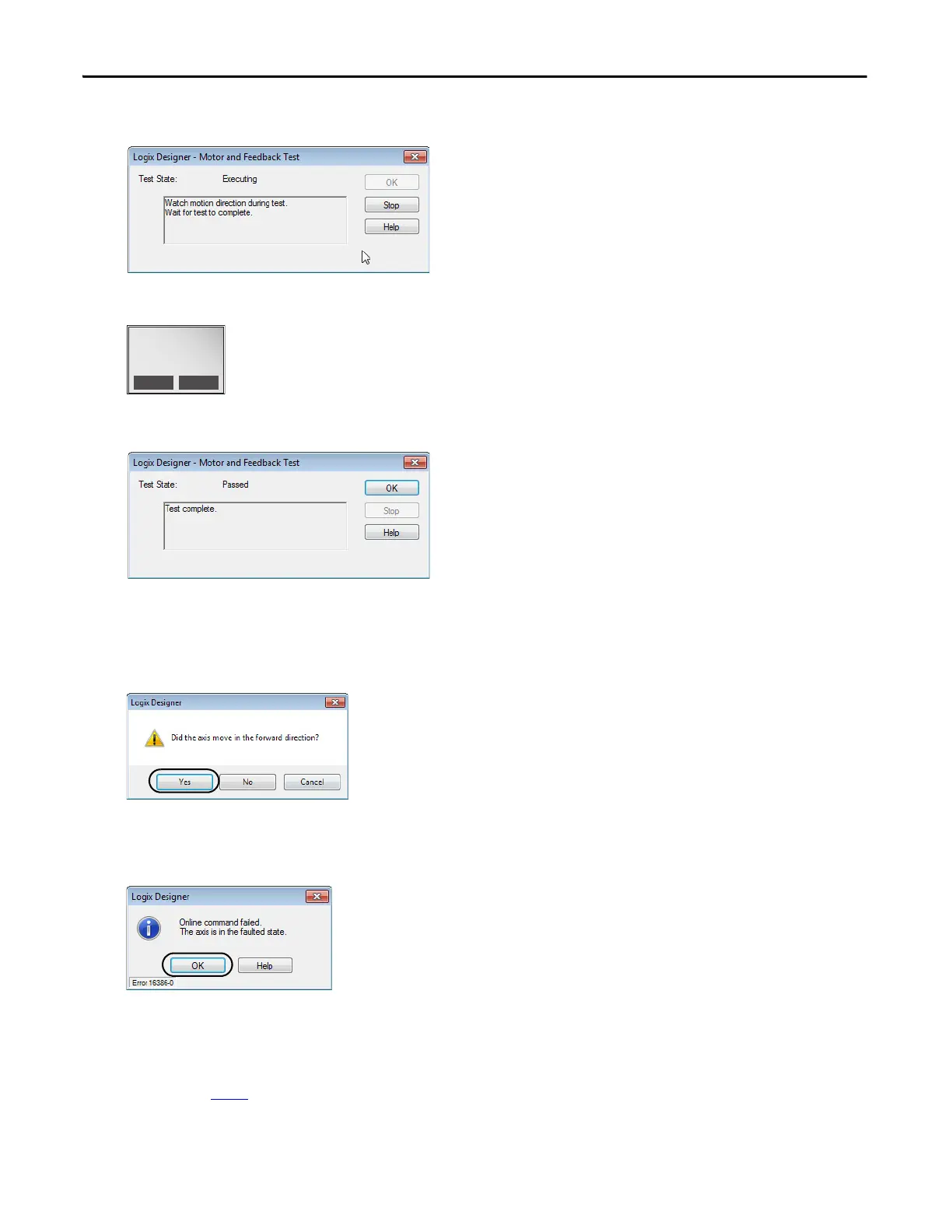
The Logix Designer - Motor and Feedback Test dialog box opens. The Test State is Executing.
TESTING appears on the drive LCD display.
When the test completes successfully, the Test State changes from Executing to Passed.
7. On the Motor and Feedback Test dialog box, click OK.
A dialog box opens asking if the direction was correct.
8. Click Yes.
9. On the Axis Properties dialog box, click Accept Test Results.
If the test fails, this dialog box opens.
a. Click OK.
b. Verify the DC bus voltage.
c. Verify unit values entered in the Scaling category.
d. Return to
step 5 and run the test again.
TESTING
192.168.1.1
DC BUS: 218.3V
SETUP
MENU
 Loading...


