Rockwell Automation Publication 2094-UM001J-EN-P - March 2017 273
RBM Module Interconnect Diagrams Appendix G
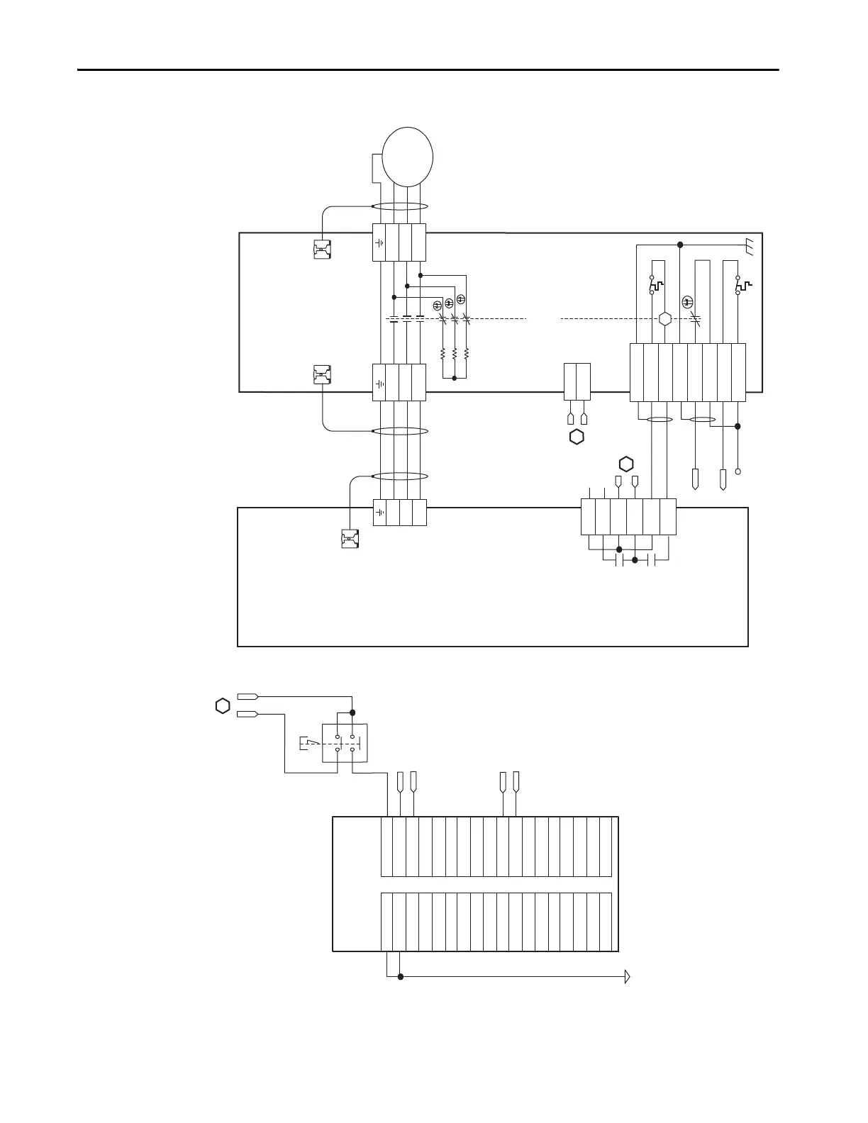
RBM Wiring Example, Category 2 Configuration per EN ISO 13849 (continued)
T2
T1
K
4
3
2
1
4
3
2
1
D
C
B
A
IO_PWR1
BRKTMP1
W
V
U
6
5
4
3
2
1
4
3
2
1
W_DRIVE
V_DRIVE
U_DRIVE
W_MTR
V_MTR
U_MTR
SHIELD
COIL_A2
COIL_A1
SHIELD
CONSTAT_42
CONSTAT_41
TS_22
TS_21
MBRK -
MBRK +
COM
PWR
DBRK -
DBRK +
8
7
6
5
4
3
2
1
BRKSTAT1
L1
L2
L3
AUX3
AUX2
AUX1
R3
R2
R1
W
V
U
GND
M
AUX4
GND-0
GND-1
GND-2
GND-3
GND-4
GND-5
GND-6
GND-7
GND-8
GND-9
GND-10
GND-11
GND-12
GND-13
GND-14
GND-15
GND-15
NOT USED
IN-0
IN-1
IN-2
IN-3
IN-4
IN-5
IN-6
IN-7
IN-8
IN-9
IN-10
IN-11
IN-12
IN-13
IN-14
IN-15
NOT USED
NOT USED
2
4
6
8
10
12
14
16
18
20
22
24
26
28
30
32
34
36
1
3
5
7
9
11
13
15
17
19
21
23
25
27
29
31
33
35
IO_COM
BRKSTAT0
BRKSTAT1
BRKTMP0
BRKTMP1
D
2
1
L2
L1
C
A
Note 3
Note 1
Note 4
Note 1
Auxiliary 230V AC
Input (TB4) Connector
(2090-XB120-xx only)
Kinetix 6000
Axis Module
2094-AMxx or
2094-BMxx
(Axis_1)
Cable Shield
Clamp
2090-XXNRB-14F0P7
RBM to Drive Interface Cable
Note 2
Motor Connections
(TB2) Connector
Drive Connections
(TB1) Connector
I/O Connections
(TB3) Connector
Motor/Resistive
Brake (BC) Connector
Motor Power
(MP) Connector
Cable Shield
Clamp
Cable Shield
Clamp
Motor Power
Connections
Bulletin 2090
Resistive Brake Module
2090-XBxx-xx
(RBM_1)
Note 1
Note 3
* Indicates User Supplied Component
Latching
Pushbutton *
ControlLogix Input Device
1756-IB16
Refer to the wiring examples in
Appendix A for motor power
cable catalog numbers.
Note 2

 Loading...


