108 Rockwell Automation Publication 6000-UM002E-EN-P - April 2018
Chapter 5 Preventative Maintenance and Component Replacement
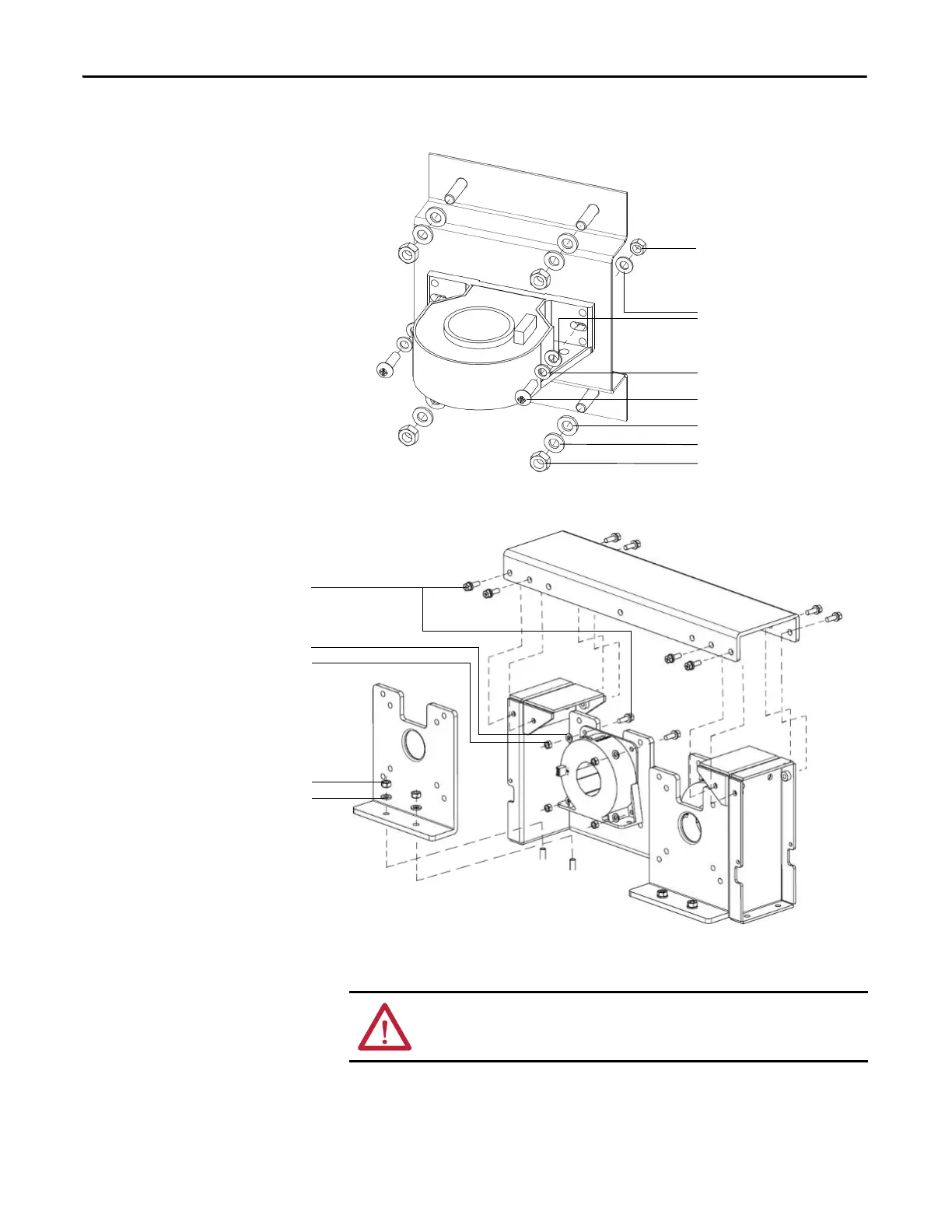
Figure 40 - Exploded view of the HECS and Mounting Bracket (Power Module rating <200 A)
Figure 41 - Exploded view of the HECS and Mounting Bracket (Power Module rating 200...680 A)
5. Install the HECS on the Mounting Bracket using the existing hardware.
6. Install the Mounting Bracket to the cabinet using existing hardware.
M5 x 16 cross pan head screw
M6 nut
Ø5 lock washer
M5 nut
Ø5 washer
Ø6 lock washer
Ø6 washer
M5 x 16 cross pan head screw
M6 nut
Ø5 washer
M5 nut
Ø6 washer
ATTENTION: Verify that the current sampling direction is correct. This is
indicated by an arrow symbol on the top of the HECS.

 Loading...


