EasyManuals Logo

Allen-Bradley PowerFlex 6000 User Manual

Allen-Bradley PowerFlex 6000
146 pages
To Next Page IconTo Next Page
To Previous Page IconTo Previous Page
Page #123 background imageLoading...
Page #123 background image
Rockwell Automation Publication 6000-UM002E-EN-P - April 2018 123
Preventative Maintenance and Component Replacement Chapter 5
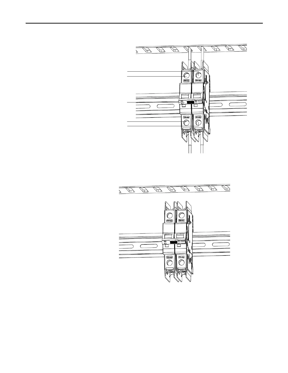
Figure 54 - Screw location on Circuit Breaker
4. Release the spring-loaded latches at the bottom of the circuit breaker and
lift the circuit breaker off the DIN rail.
Figure 55 - Release spring-loaded latch on LV Circuit Breakers
5. Install the new circuit breaker in reverse order of removal.
Circuit breaker switch must
be in the Off position
Loosen screws and
remove wires
Loosen screws and
remove wires

Table of Contents

Other manuals for Allen-Bradley PowerFlex 6000

Questions and Answers:

Question and Answer IconNeed help?

Do you have a question about the Allen-Bradley PowerFlex 6000 and is the answer not in the manual?

Allen-Bradley PowerFlex 6000 Specifications

General IconGeneral
BrandAllen-Bradley
ModelPowerFlex 6000
CategoryDC Drives
LanguageEnglish

Related product manuals