28 Rockwell Automation Publication 6000-UM002E-EN-P - April 2018
Chapter 2 Drive System Layout
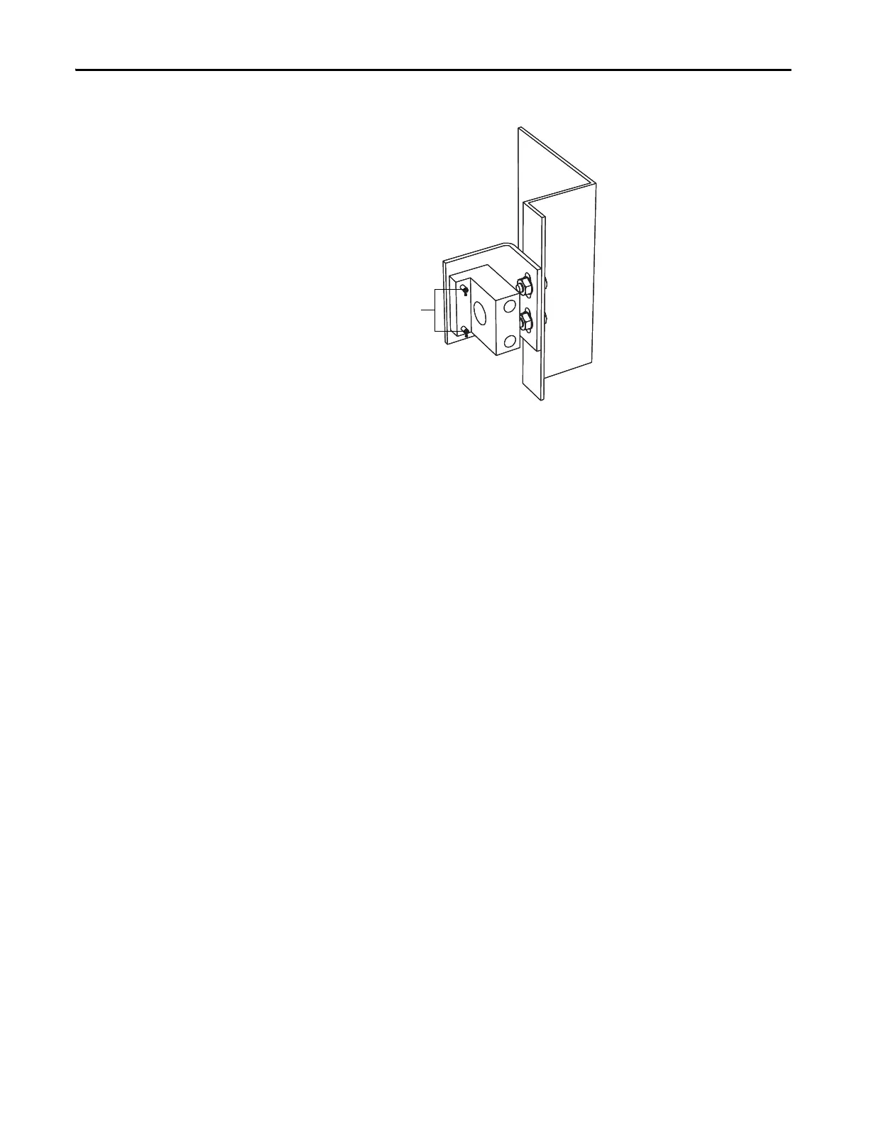
Figure 18 - Dead Bolt Counterpart Mounted to Cabinet
4. Bolt the cabinet door closed so the pins on the dead bolt counterpart make
contact with the dead bolt assembly. Doing so should leave two marks of
torque sealant or grease on the assembly where the pins made contact (See
Figure 13).
5. Slightly loosen the adjustment bolts on the counterpart and make the
necessary movements on the counterpart to ensure that the pins align with
the landing plates on the dead bolt assembly. As the amount of counterpart
movement required is an estimate, it may take a couple attempts to
properly align the assembly.
6. Clean the torque seal/grease from the key interlock once finished aligning
the counterpart.
Once properly aligned, the key should turn freely when the cabinet door is fully
bolted shut. If the key does not function when the door is tightly bolted closed,
adjustments will have to be made to the depth of the counterpart. This can be
done by adding shims on the landing plate where the counterpart is mounted.
Besides the mechanical interlock, PowerFlex 6000 drives also provide
Guardmaster® safety limit switch on each cabinet door that interlocks with input
switching devices.
When any of the cabinet doors are open, the drive will turn off the IGBT output.
At the same time, a trip signal will be sent to the circuit breaker to open the
circuit.
Two pairs of passive dry contacts (open and close) are provided to the user.
Place grease on
dead bolt pins here

 Loading...


