Rockwell Automation Publication 6000-UM002E-EN-P - April 2018 27
Drive System Layout Chapter 2
Interlocking key “KB” is used to open the left door of the isolation transformer
cabinet, or the left and right doors of the power module cabinet.
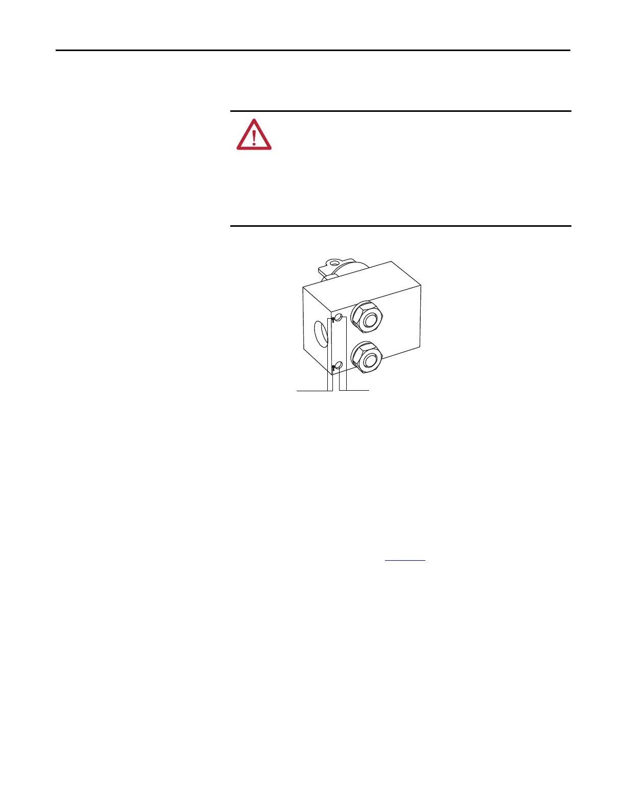
Figure 17 - Dead Bolt Assembly Mounted to Door
1. Lock out and isolate the drive from medium voltage. Verify with a hot
stick that there is no medium voltage present.
2. Determine that the key interlock is correctly aligned by securely bolting
the medium voltage doors of the cabinet closed and removing from the
lock. The key should turn easily; if any force is required to turn the key, the
dead bolt alignment requires adjustment.
3. Open the doors of the cabinet and inspect the key assembly. Place high
visibility grease on the pins of the dead-bolt counterpart. The factory
recommends using yellow torque sealant, however if it is unavailable
almost any grease will do (See Figure 17
).
ATTENTION: Servicing energized industrial control equipment can be
hazardous. Severe injury or death can result from electrical shock, burn, or
unintended actuation of control equipment. Hazardous voltages may exist in
the cabinet even with the circuit breaker in the off position. Recommended
practice is to disconnect or lock out control equipment from power sources, and
confirm discharge of stored energy in capacitors. If it is necessary to work in the
vicinity of energized equipment, the safety related work practices of NFTA 70E,
Electrical Safety requirements for Employee Work places, must be followed.
Grease marks from
dead bolt pins
Adjust dead bolt counterpart so that
grease marks from pins hit here

 Loading...


