96 Rockwell Automation Publication 6000-UM002E-EN-P - April 2018
Chapter 5 Preventative Maintenance and Component Replacement
3. Remove and retain four M6 x 12 hexagon screws from the top of the fan
support bracket, and remove the bracket from the fan assembly.
4. Remove the wiring cover and disconnect the wiring.
5. Install the fan in the reverse order of its removal. Rotate the impeller by
hand to ensure that there is no contact with the fan housing assembly.
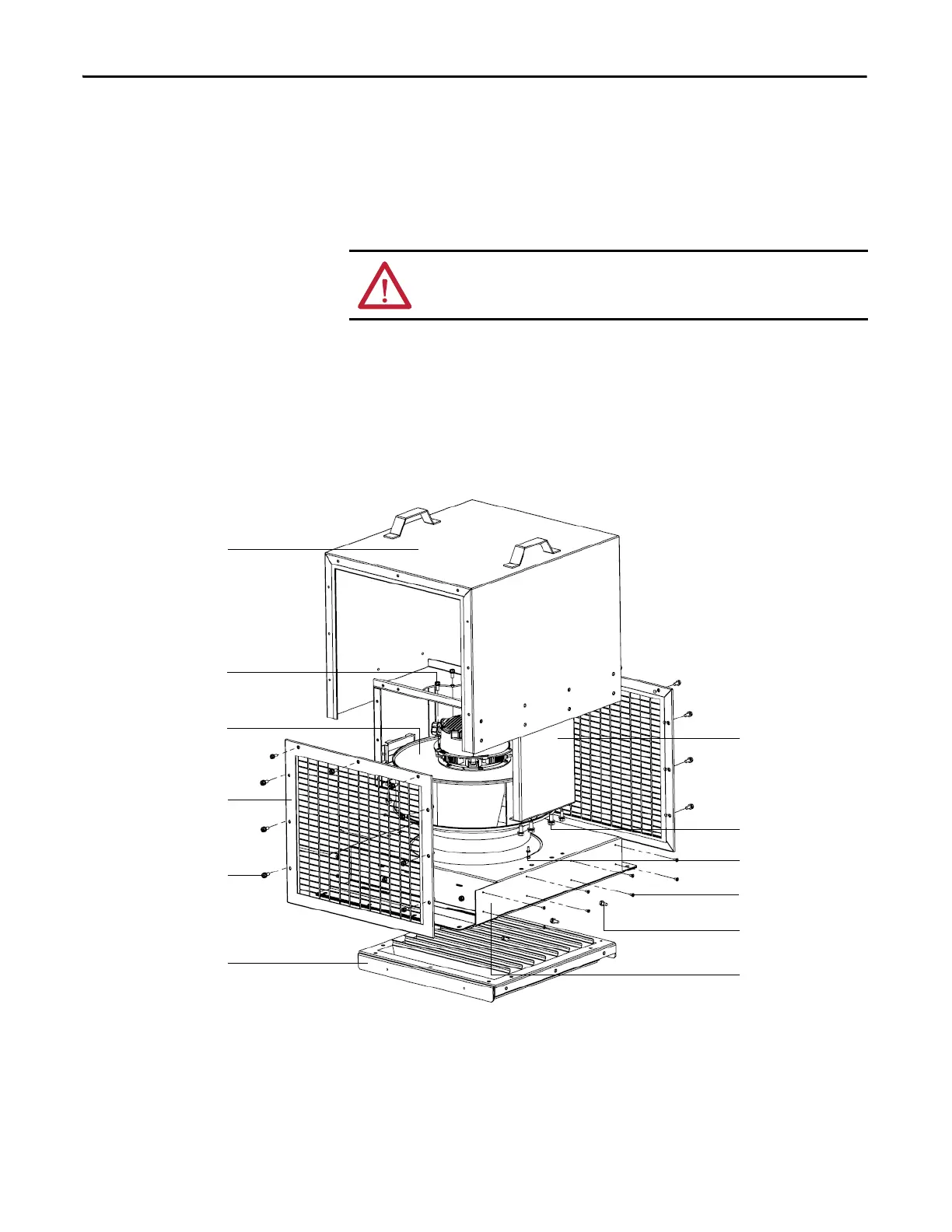
Replace Fan for Type B Fan Housing
1. Remove and retain 18 M6 x 16 hexagon socket screws around the wire
screen frame, and remove the frame.
2. Remove and retain 16 M4 x 8 countersunk head screws that secure the fan
housing lid, and remove the lid.
3. Remove and retain 10 M6 x 16 hexagon combination screws that secure
the horizontal louver, and remove the louver.
4. Disconnect the fan from the terminal block.
5. Remove and retain eight M8 x 20 hexagon combination screws that secure
the fan support bracket, and remove the bracket.
ATTENTION: The fan must be handled with extreme care. Failure to do so can
alter the fan balance and will negatively impact performance and life span.
M6 x 16 hexagon
combination screw (5)
M6 x 16 hexagon
socket screw (18)
Fan housing lid
Fan support bracket
Wire screen frame
Horizontal louver
M8 x 20 hexagon
combination screw (8)
Terminal block
M4 x 12 hexagon
combination screw (4)
Fan housing assembly
M4 x 8 countersunk
head screw (16)
M6 x 16 hexagon
combination screw (10)

 Loading...


