EasyManuals Logo

Allen-Bradley Rockwell Automation 1734-AENT User Manual

Allen-Bradley Rockwell Automation 1734-AENT
158 pages
To Next Page IconTo Next Page
To Previous Page IconTo Previous Page
Page #25 background imageLoading...
Page #25 background image
9 Publication 1734-UM011D-EN-P - May 2011
Chapter
2
Install the Adapter
What This Chapter Contains
This chapter describes how to physically install the adapter on the DIN rail
and connect it to the EtherNet/IP network. The following table lists where to
find specific information.
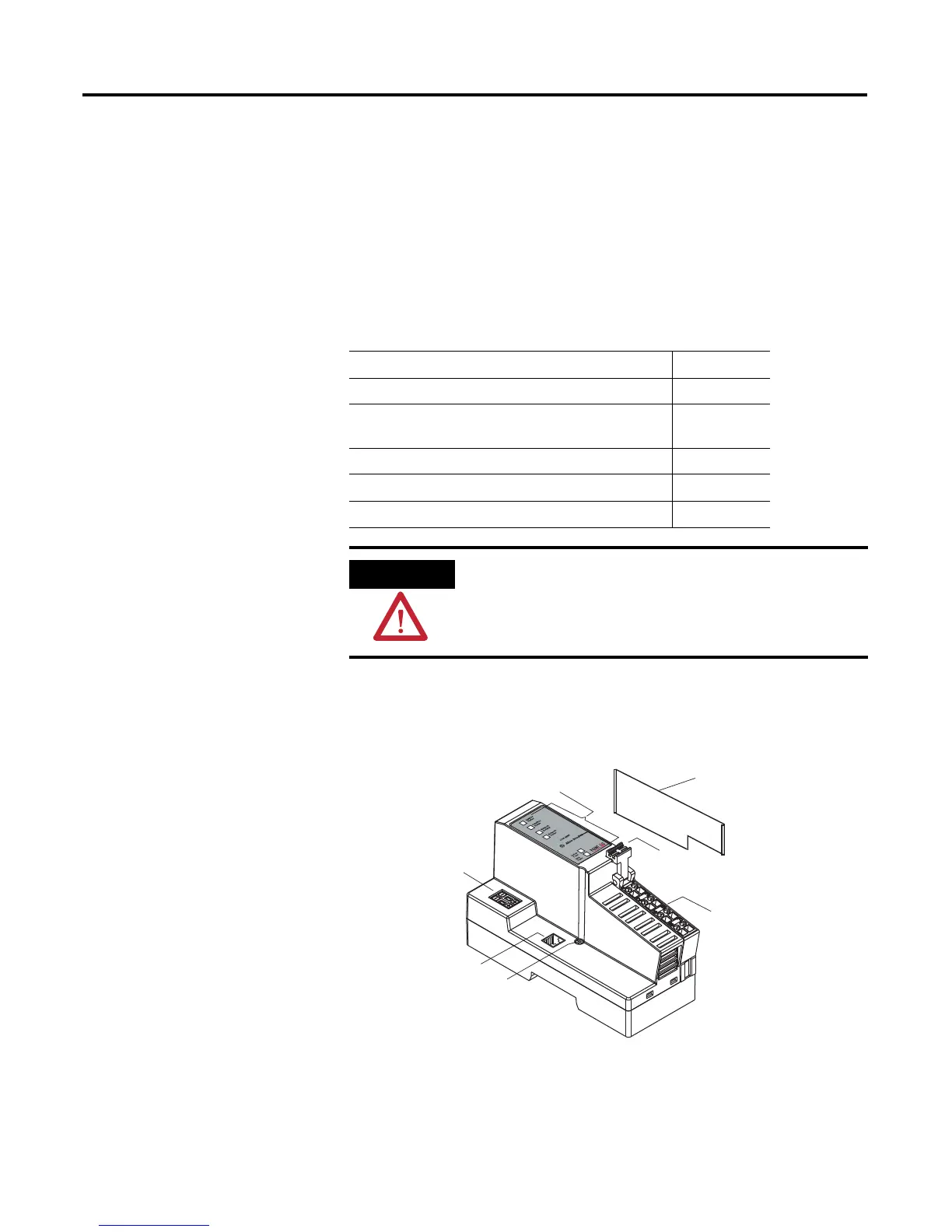
Identify Adapter
Components
Use the figure to identify the external features of the adapter.
Topic Page
Identify Adapter Components 9
Mount the Adapter on a DIN Rail Before Installing
Modules
10
Mount or Replace the Adapter to an Existing System 11
Wire Your Adapter 12
Mounting Dimensions 13
ATTENTION
You must use series C POINT I/O modules with the 1734-AENT
adapter. Series A or B POINT I/O modules will not work with
this adapter.
Safety end cap
LED indicators
Node address
thumbwheel
EtherNet
network
RJ45
connector
DIN rail
locking screw
(orange)
RTB
removable
handle
Removable Terminal
Block (RTB)
31533-M

Table of Contents

Other manuals for Allen-Bradley Rockwell Automation 1734-AENT

Questions and Answers:

Question and Answer IconNeed help?

Do you have a question about the Allen-Bradley Rockwell Automation 1734-AENT and is the answer not in the manual?

Allen-Bradley Rockwell Automation 1734-AENT Specifications

General IconGeneral
Model1734-AENT
CategoryNetwork Hardware
TypeEtherNet/IP Adapter
Ethernet Ports2
IP AddressingStatic or DHCP
Network AddressConfigurable via software
MountingDIN rail
Number of Ports2
Port TypeRJ45
Communication ProtocolEtherNet/IP
ManufacturerRockwell Automation
Power Supply24V DC
EnclosureOpen-style

Related product manuals