EasyManuals Logo

Allen-Bradley Rockwell Automation 1734-AENT User Manual

Allen-Bradley Rockwell Automation 1734-AENT
158 pages
To Next Page IconTo Next Page
To Previous Page IconTo Previous Page
Page #28 background imageLoading...
Page #28 background image
Publication 1734-UM011D-EN-P - May 2011
12 Install the Adapter
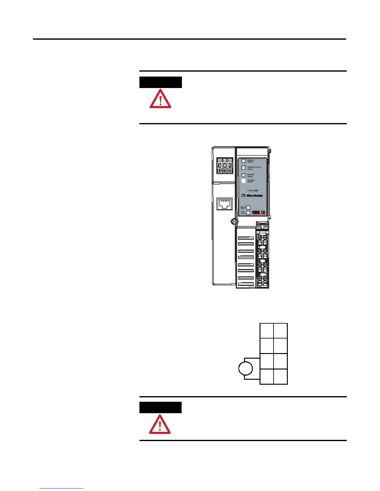
Wire Your Adapter
Refer to the illustration to wire the adapter.
If you connect or disconnect wiring while the field-side power is
on, an electrical arc can occur. This could cause an explosion in
hazardous location installations.
Be sure that power is removed or the area is nonhazardous
before proceeding.
ATTENTION
Do not connect 120/240V AC power to this supply.
43264
System Power
CHAS GND
C
V
NC
Network address
Thumbwheels
Field Power
NC = No Connection
CHAS GND = Chassis Ground
C = Common
V = Supply
Module status
Network activity status
Network status
Ethernet RJ-45
connector
POINTBus status
V DC
NC
C
V
NC
Chas
Gnd
C
V
0
4
2
6
Chas
Gnd
12/24V DC
This DC supply will be
connected to the
internal power bus.
1
5
3
7

Table of Contents

Other manuals for Allen-Bradley Rockwell Automation 1734-AENT

Questions and Answers:

Question and Answer IconNeed help?

Do you have a question about the Allen-Bradley Rockwell Automation 1734-AENT and is the answer not in the manual?

Allen-Bradley Rockwell Automation 1734-AENT Specifications

General IconGeneral
Model1734-AENT
CategoryNetwork Hardware
TypeEtherNet/IP Adapter
Ethernet Ports2
IP AddressingStatic or DHCP
Network AddressConfigurable via software
MountingDIN rail
Number of Ports2
Port TypeRJ45
Communication ProtocolEtherNet/IP
ManufacturerRockwell Automation
Power Supply24V DC
EnclosureOpen-style

Related product manuals