Publication 1747-RM001G-EN-P - November 2008
13-8 SLC Communication Channels
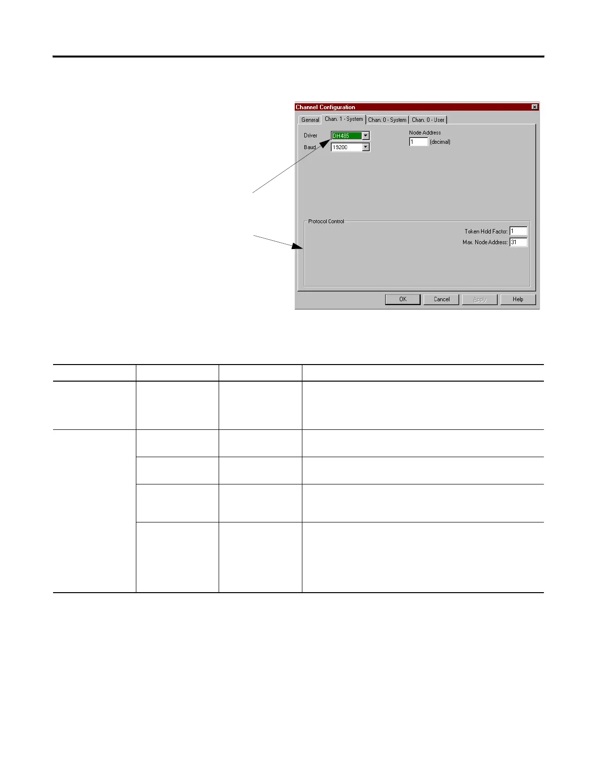
1. On the Channel 1 or 0 tab,
choose DH-485 for your Driver.
2. Configure the communication
driver characteristics
according to Table 13.2.
Table 13.2 Define these communication parameters when configuring an SLC 5/03 or higher processor for DH-485
communications.
Tab Parameter Default Selections
General Diagnostic File 0 Select an unused file (9 to 255) to store channel status
information. You must define a diagnostic file in order to be able to
view channel 0 or channel 1 status. See Table 13.3 for a file
description.
Channel 0 or Channel
1 System
Baud Rate 19200 Toggles between the communication rate of 1200, 2400, 9600, and
19200.
Node Address 1 This is the node address of the processor on the DH-485 network.
The valid range is 1 to 31.
Max Node Address 31 This is the maximum node address of an active processor. The
valid range is 1 to 31. The SLC 500 Fixed, SLC 5/01 and SLC 5/02
processors are factory set to 31.
Token Hold Factor 1 Determines the number of transactions allowed to make each
DH-485 token rotation. Increasing this value allows your processor
to increase its DH-485 throughput. This also decreases throughput
to other processors on the DH-485 link. The valid range is 1 to 4 for
SLC 5/03 and higher processors. The SLC 500 Fixed, SLC 5/01 and
SLC 5/02 processors are factory set to 1.

 Loading...


