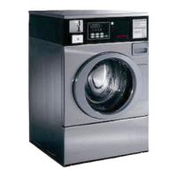
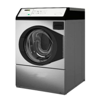
1. Service Door
2. Control Panel
Figure 2
OPL Models
Preparing for Manual Mode
Manual programming requires the user to remove the cabinet top
or control panel and unplug the bullet connector located between
the “white/black” and “red/blue” wires. This will allow the user
to access various programming options, diagnostics, and audit ca-
pabilities. Refer to Figure 3 .
Single Units
1. Remove the screws from the back of the top panel that attach
the top panel to the machine.
2. From the back of the machine, using a screwdriver, pry the
top panel upward and towards you.
3. Remove the screws from the top of the control panel that at-
tach the control panel to the machine.
4. Remove the screws from the bottom of the control panel that
attach the control panel to the machine.
NOTE: When reinstalling the control panel, be sure to
align the control panel’s tabs with the machine’s tabs.
Stack Units
1. Remove the screws from the bottom of the dryer front panel.
2. Remove the screws that attach the bottom of the dryer base to
the frontload washer’s control panel.
3. To gain access to the control panel’s components, tilt the dry-
er back slightly and insert a 27-inch 2 x 2 between the dryer
and washer.
4. As an alternative, remove the control panel using putty kni-
ves.
a. Insert a thin putty knife between the frontload washer’s
control panel and front panel to disengage the control pan-
el’s tabs.
b. The control panel’s tabs are located 8.71 inches from the
edge of the left and right side panels.
Opening the Service Door
©
Published by permission of the copyright owner -
DO NOT COPY or TRANSMIT
21 Part No. 805405ENR5