Chapter : Chapter 1: Overview
32
LEDs
This section describes the four types of LEDs on GS970M Series
switches:
“POWER and FAULT LEDs” on page 32
“10/1000BASE-T/100BASE-TX Link/Activity/Speed LED and PoE
status LED” on page 34
“10/1000BASE-T/100BASE-TX Link/Activity/Speed LED and
Duplex/Collision LED” on page 36
“SFP LEDs” on page 38
“SD card LED” on page 39
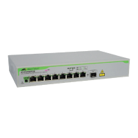
POWER and
FAULT LEDs
The POWER LED reports the status of AC power and is located on the
front panel of the of the switches beside the console port. See
Figure 17.
All port LEDs are OFF when the switch is operating in the low power
mode. To toggle on the LEDs, use the ecofriendly button. See
“ecofriendly button” on page 41 for more information.
FIGURE 17. POWER LED ON A GS970M SERIES SWITCH
CONSOLE
RS-232
SD
FAULT
POWER
D
1000 LINK ACT 10/100 LINK ACT
2
1
ess Label

 Loading...