GS9790M Series Switch Installation Guide
55
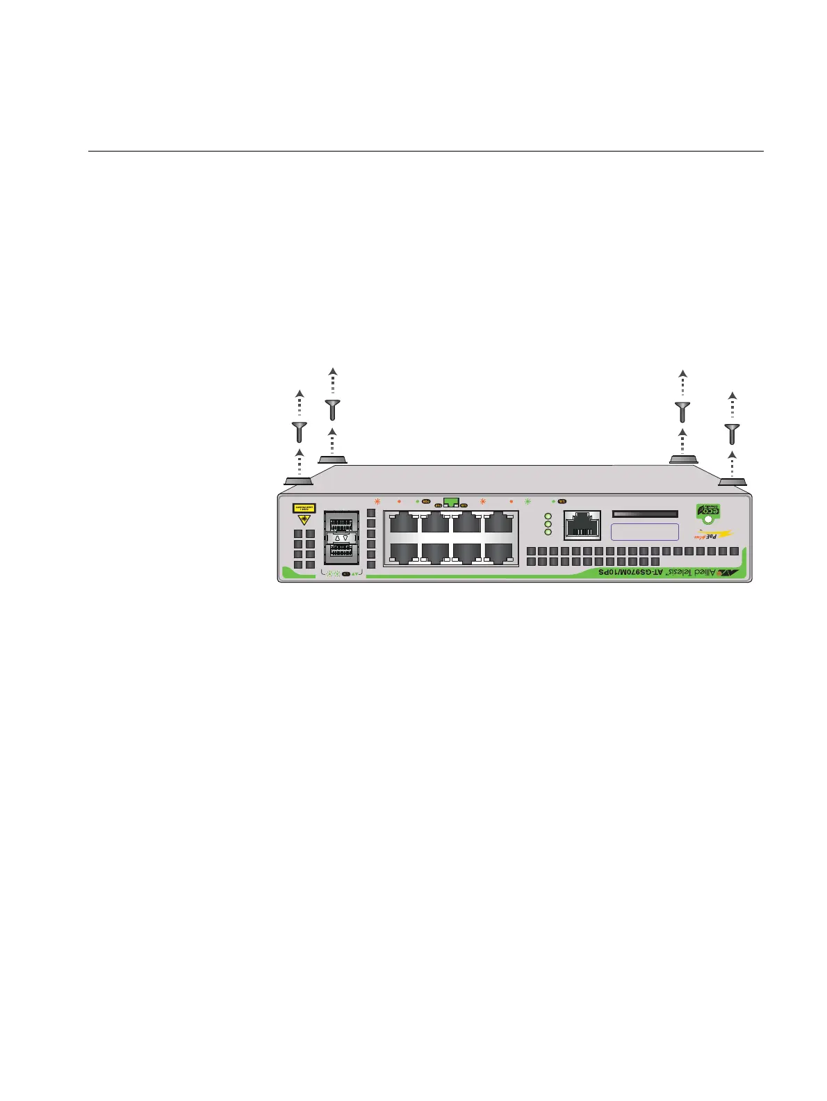
Removing the feet from a switch before installing it in an equipment
rack or on a wall
Before you install the switch in a 19-inch equipment rack or on a wall, you
need to remove the rubber feet, if they are attached to the base of the
switch. To do this, follow these steps:
1. Place the unit upside down on a level, secure surface.
2. Remove the rubber feet with a screwdriver. Figure 25 shows how to do
this on a GS970M/10PS switch.
F
IGURE 25. REMOVING THE RUBBER FEET FROM A SWITCH
3. Turn the switch back over.
CONSOLE
RS-232
SD
FAULT
POWER
SD
1000 LINK ACT 10/100 LINK ACT PD ON PD ERR MAX CURRENT
SFP
9
10
24 68
1357
MAC Address Label
CONSOLE
RS-232
SD
FAU LT
POWER
SD
1000 LINK ACT 10/100 LINK ACT PD ON PD ERR MAX CURRENT
SFP
9
10
24 68
1357
MAC Address Label

 Loading...