EasyManuals Logo

Allied Telesis CentreCOM GS970M Series User Manual

Allied Telesis CentreCOM GS970M Series
100 pages
To Next Page IconTo Next Page
To Previous Page IconTo Previous Page
Page #48 background imageLoading...
Page #48 background image
Chapter : Chapter 1: Overview
38
SFP LEDs The GS970M Series switches have SFP Link/Activity LEDs on the front
panel. See
Figure 21.
The SFP Link/Activity LEDs indicate the activity status for each SFP slot.
Each SFP slot has ONE uni-color LED:
The LEFT LED corresponds to the UPPER SFP port
The RIGHT LED corresponds to the LOWER SFP port
Note
All of the port LEDs are OFF when the switch is operating in the low
power mode. To toggle on the LEDs, use the ecofriendly button. See
“ecofriendly button” on page 41 for more information.
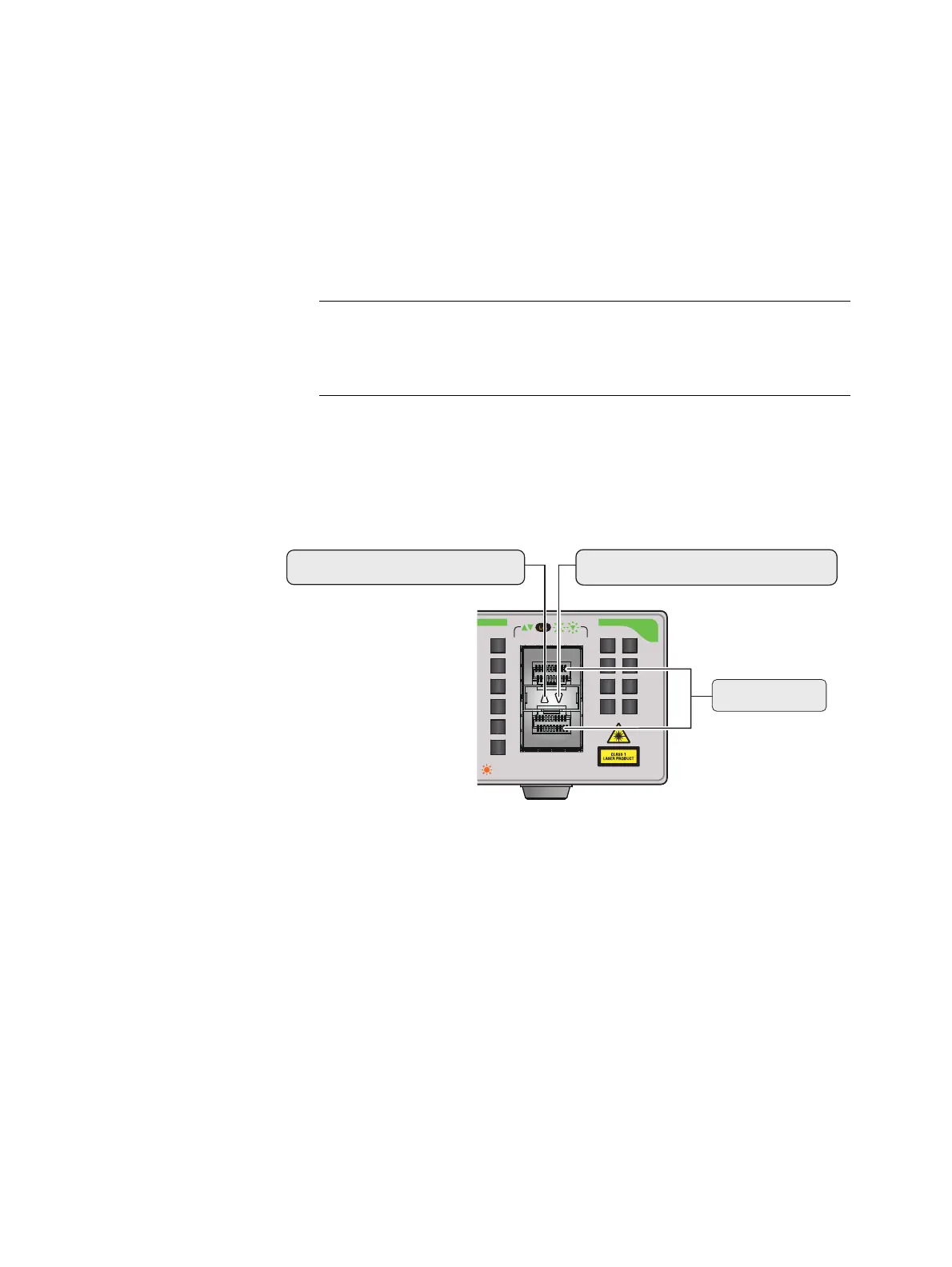
FIGURE 21. SFP LINK/ACTIVITY LEDS ON A GS970M SERIES SWITCH
MAX CURRENT
SFP
9
10
SFP slots
Upper (left) SFP LED
Lower (right) SFP LED

Table of Contents

Other manuals for Allied Telesis CentreCOM GS970M Series

Questions and Answers:

Question and Answer IconNeed help?

Do you have a question about the Allied Telesis CentreCOM GS970M Series and is the answer not in the manual?

Allied Telesis CentreCOM GS970M Series Specifications

General IconGeneral
BrandAllied Telesis
ModelCentreCOM GS970M Series
CategorySwitch
LanguageEnglish

Related product manuals