Appendix : Appendix A: Technical Specifications
88
Connectors and port pinouts
This section lists the connectors and connector pinouts.
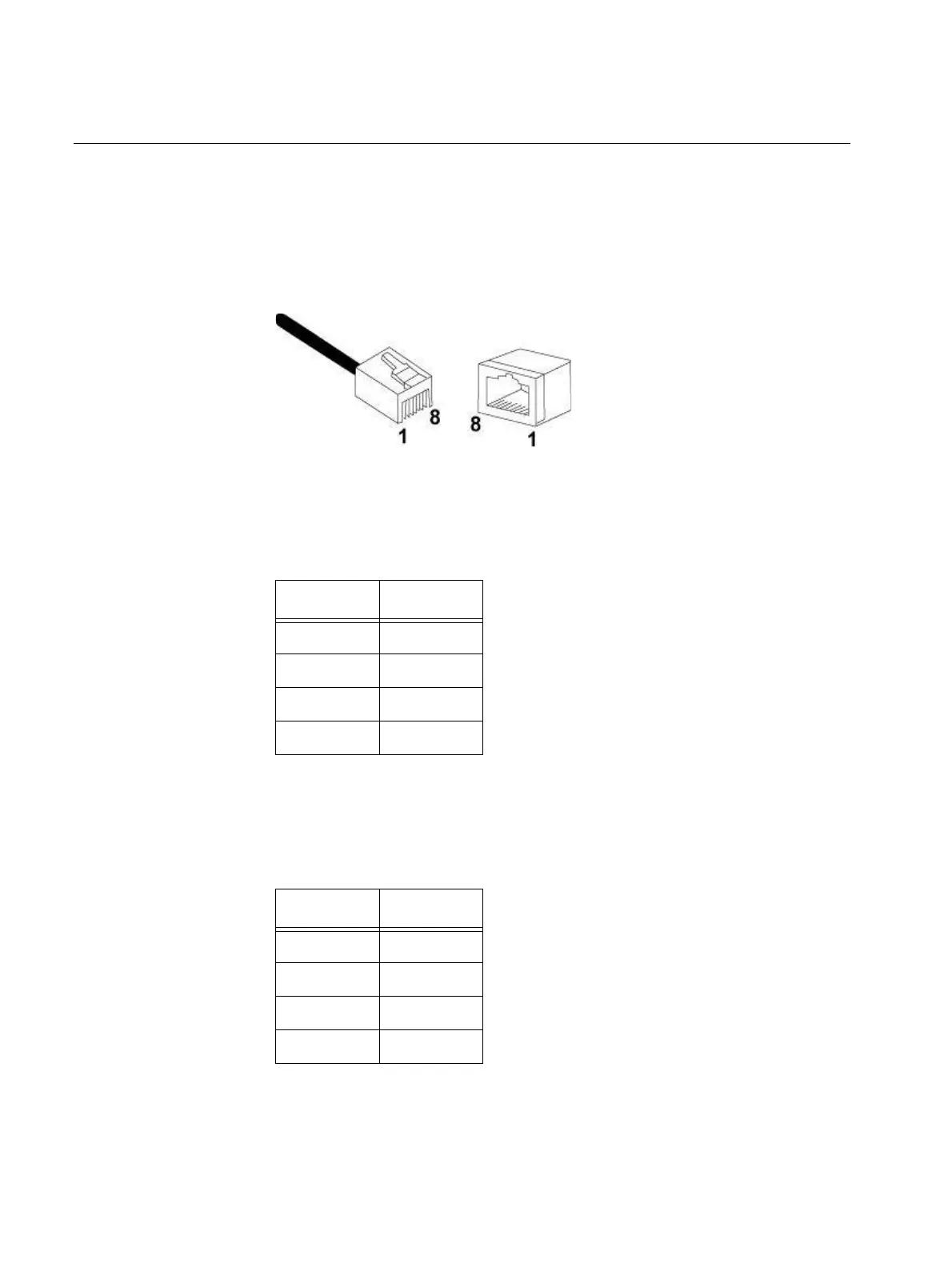
Figure 53 illustrates the pin layout for an RJ45 connector and port.
F
IGURE 53. RJ45 CONNECTOR AND PORT PIN LAYOUT
Table 18 lists the RJ45 pin signals when a twisted pair port is operating in
the MDI configuration.
T
ABLE 18. MDI PIN SIGNALS (10BASE-T OR 100BASE-TX)
Pin Signal
1 TX+
2 TX-
3 RX+
6 RX-
Table 19 lists the RJ45 port pin signals when a
twisted pair port is
operating in the MDIX configuration.
T
ABLE 19. MDIX PIN SIGNALS (10BASE-T OR 100BASE-TX)
Pin Signal
1 RX+
2 RX-
3 TX+
6 TX-

 Loading...