GS9790M Series Switch Installation Guide
67
Installing a GS970M/18, GS970M/28 or AT-GS970M PS Series switch
on a wall
These instructions show you how to install a GS970M/18, GS970M/28 or
AT-GS970M PS Series switch on a wall. The wall mount kit is AT-BRKT-
J24 and can be purchased separately from your Allied Telesis dealer.
This section shows a GS970M/10PS switch as an example.
Before you start, ensure that the wall is sturdy enough to hold the switch’s
weight. You may need to position the switch so that it can be screwed into
the wall’s framing timber or an equivalent structural element.
To install the switch on a wall, perform the following procedure:
1. If the rubber feet are attached to the bottom of the switch, remove
them with a screwdriver (
Figure 25 on page 55), then turn the switch
back over.
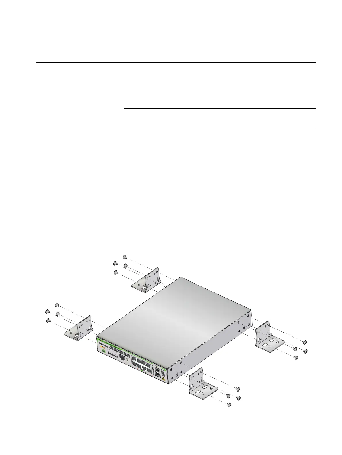
2. Orient the brackets against the sides of the switch as shown in Figure
41, and secure them to the unit with the 16 brackets screws included in
the wall mount kit.
FIGURE 41. ATTACHING WALL MOUNT BRACKETS TO THE SIDE OF THE SWITCH
CONSOLE
RS-232
SD
FAULT
POWER
SD
1000 LINK
ACT
10/100 LINK
ACT
PD ON PD ERR MAX CURRENT
SFP
9
10
24 68
1357
MAC Address Label

 Loading...