GS9790M Series Switch Installation Guide
33
Table 5 describes the POWER LED for GS970M Series switches.
T
ABLE 5. POWER LED FUNCTIONAL DESCRIPTIONS
LED State
Description
POWER
Off
Indicates either the switch is no
t receiving AC
power or the AC input power is operating outside
the normal range
Steady
green
The switch is receiving AC input power and is
ope
rating normally
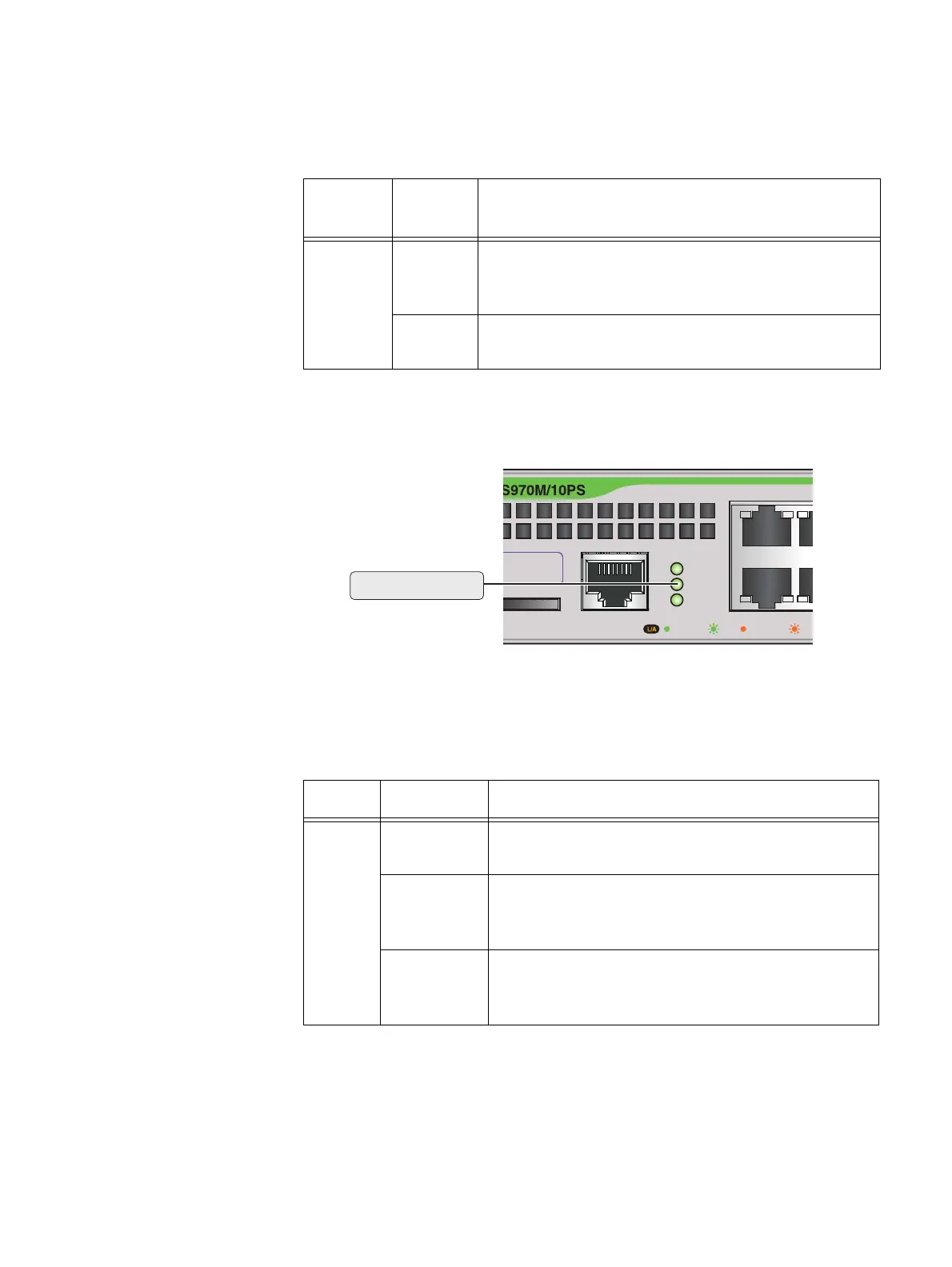
Figure 18 shows the location of the FAULT LED.
F
IGURE 18. FAULT LED ON A GS970M SERIES SWITCH
Table 6 describes the functions of the FAULT LED.
T
ABLE 6. FAULT LED FUNCTIONAL DESCRIPTIONS
LED State Description
FAULT
Off
The switch is receiving AC input power and is
o
perating normally
Red
flashing
on
ce
Indicates fan failure
Red
f
lashing six
times
Indicates the switch’s temperature has
e
xceeded the threshold
CONSOLE
RS-232
SD
FAULT
POWER
D
1000 LINK ACT 10/100 LINK ACT
2
1
ress Label

 Loading...