Chapter : Chapter 2: Installation
68
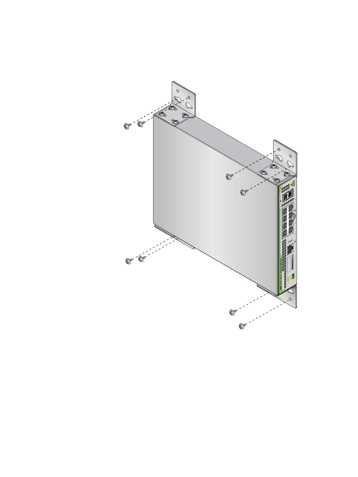
3. While another person holds the switch at the wall location, secure it to
the wall using the eight wall mounting screws (
Figure 42).
FIGURE 42. SECURING THE SWITCH TO THE WALL
4. Go to “Cabling the switch” on page 69.
CONSOLE
RS-232
SD
FAULT
POWER
SD
1000 LINK ACT 10/100 LINK ACT PD ON PD ERR MAX CURRENT
SFP
9
10
24 68
1357
MAC Address Label

 Loading...