EasyManuals Logo

Allied Telesis x530L Series User Manual

Allied Telesis x530L Series
228 pages
To Next Page IconTo Next Page
To Previous Page IconTo Previous Page
Page #100 background imageLoading...
Page #100 background image
Chapter 3: Beginning the Installation
100
Figure 38 lists the items in the accessory kit. Contact your Allied Telesis
sales representative for assistance if any item is missing or damaged.
Figure 38. x530L-18GHXm Switch Accessory Kit
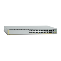
One 2m (6.6 ft) local management
cable with RJ-45 (8P8C) and DB-9 (D-
sub 9-pin) connectors.
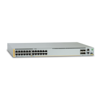
Sixteen screws for attaching the
wall/equipment rack brackets to the
switch.
Length: 6.0mm (0.2 in.)
Diameter: 4.0mm (0.2 in.)
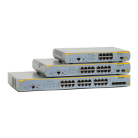
One regional AC power cord
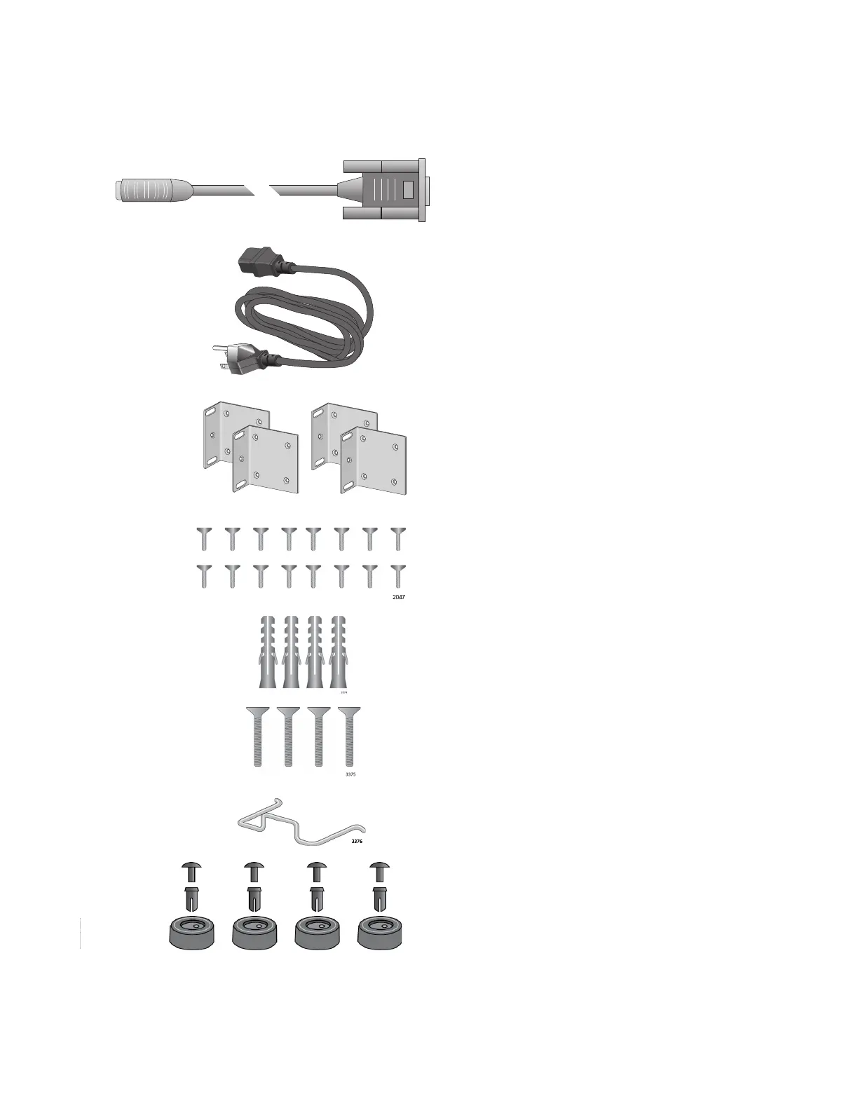
Four anchors for concrete walls:
Length: 29.6mm (1.2 in.)
Diameter: 6.0mm (0.2 in.)
Four screws for wood or concrete
walls:
Length: 32mm (1.3 in.)
Diameter: 4mm (0.2 in.)
Power cord retaining clip
1417
1570
Four wall mounting brackets
Four rubber bumper feet
1947
1947

Table of Contents

Questions and Answers:

Question and Answer IconNeed help?

Do you have a question about the Allied Telesis x530L Series and is the answer not in the manual?

Allied Telesis x530L Series Specifications

General IconGeneral
BrandAllied Telesis
Modelx530L Series
CategorySwitch
LanguageEnglish

Related product manuals