x530L Series Installation Guide for Virtual Chassis Stacking
131
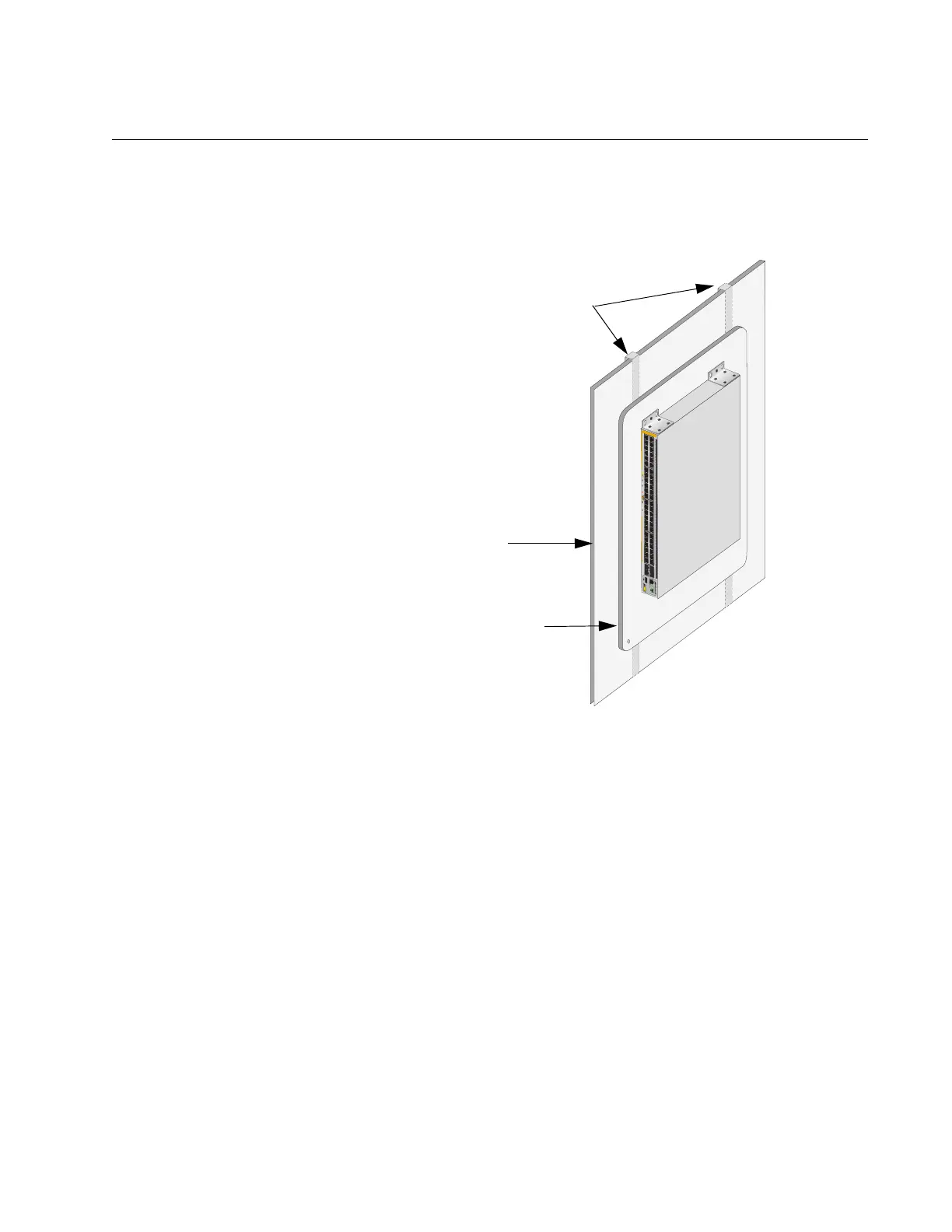
Plywood Base for a Wall with Wooden Studs
If you are installing the switch on a wall that has wooden studs, use
plywood base for the device. (A plywood base is not required for a
concrete wall.) Refer to Figure 72.
Figure 72. Switch on the Wall with a Plywood Base
Mount the plywood base to two studs in the wall. The recommended
minimum dimensions of the plywood base for the switch are:
Width: 55.9 centimeters (22 inches)
Height: 61.0 centimeters (24 inches)
Thickness: 2.5 centimeters (1 inch)
The dimensions assume the wall studs are 41 centimeters (16 inches)
apart. You might need to adjust the width of the base if the distance
between the studs in your wall is different than the industry standard.
4592
51/S1
52/S2
49
SFP+
50
351
7
9
11
13
15 17
19
21
2
3
468
10 12
2
16 18
20
14
22
24
27 29
25
31
33
35
37 39 41
43
45 47
28 30 32
34
36
26
40 42
44
38
46 48
10G
/
1G
1G LINK
ACT
100 LINK
ACT
P
D
ON
PD ERR
MAX CURRENT
AT-x530L-52GPX
CONSOLE
CL
A
S
S
1
L
E
SER PRO
DUCT
Wall Studs
Wall
Plywood Base

 Loading...


