x530L Series Installation Guide for Virtual Chassis Stacking
39
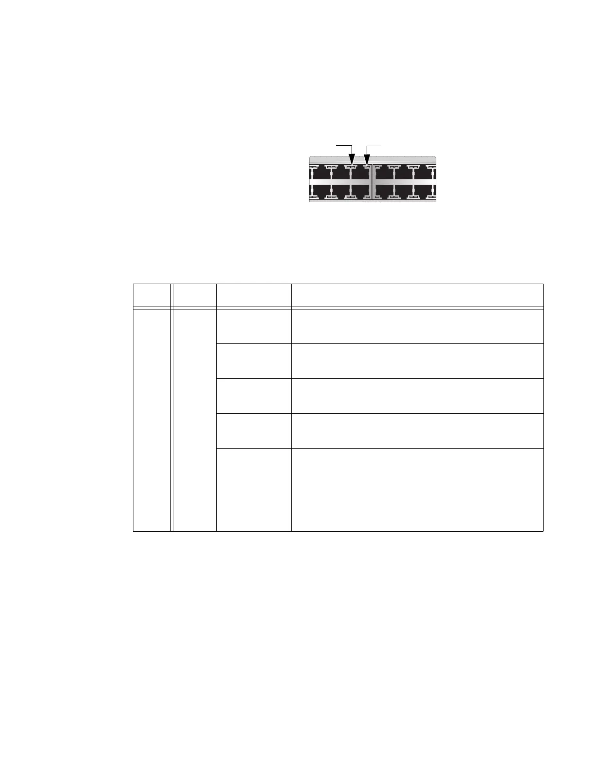
x530L-28GPX
The LEDs indicate Link/Activity (L/A) and PoE (PD ON/PD ERR/MAX
CURRENT) information. These LEDs are shown in Figure 16.
Figure 16. x530L-28GPX Twisted Pair Ports
The states of the x530L-28GTX LEDs are described in Table 12.
7 9 11 13 15 17
16 1814
81012
Table 12. x530L-28GPX Twisted Pair Ports 1 - 24 LED Functions
LED Ports State Description
L/A 1 - 24
Solid Green The port has established a 1Gbps link to a network
device.
Flashing
Green
The port is transmitting or receiving data at 1Gbps.
Solid Amber The port has established a 10Mbps or 100Mbps link
to a network device.
Flashing
Amber
The port is transmitting or receiving data at 10Mbps
or 100 Mbps.
Off Possible causes of this state are:
- The port has not established a link with another
network device.
- The LEDs are turned off. To turn on the LEDs, use
the eco-friendly button.

 Loading...


