Chapter 1: Overview
40
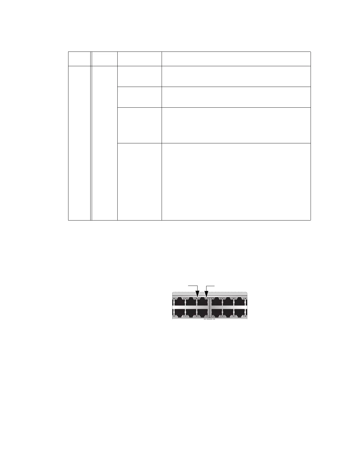
x530L-52GPX
The LEDs indicate Link/Activity (L/A) and PoE (PD ON/PD ERR/MAX
CURRENT) information. These LEDs are shown in Figure 17.
Figure 17. x530L-52GPX Twisted Pair Ports
The states of the x530L-52GPX LEDs are described in Table 13 on
page 41.
PoE 1 - 24
Solid Green PD On - The switch is delivering power to a
powered device connected to the port.
Solid Amber PD Error - The switch has shut down PoE on the
port because of a fault condition.
Flashing
Amber
PD Max Current - The switch has detected a
powered device on the port but is not delivering
power to it because doing so would exceed its
available power budget.
Off No PD - This LED state can result from the following
conditions:
- The port is not connected to a powered device or
the device is powered off.
- The port is disabled in the management software.
- PoE is disabled on the port.
- The LEDs are turned off. To turn on the LEDs, use
the eco-friendly button.
Table 12. x530L-28GPX Twisted Pair Ports 1 - 24 LED Functions (Continued)
LED Ports State Description
7 9 11 13 15 17
16 1814
81012

 Loading...


