x530L Series Installation Guide for Virtual Chassis Stacking
121
Installing the x530L-18GHXm, x530L-28GTX, x530L-28GPX, x530L-
52GTX, or x530L-52GPX Switch in an Equipment Rack
This section contains the procedure for installing the x530L-18GHXm,
x530L-28GTX, x530L-28GPX, x530L-52GTX, or x530L-52GPX Switch in a
standard 19-inch equipment rack using the brackets supplied with the unit.
Required Items The following items are required to install the switch in an equipment rack:
Two equipment rack brackets (included with the switch)
Eight M4x6mm bracket screws (included with the switch)
Cross-head screwdriver (not provided)
Four standard equipment rack screws (not provided)
Switch
Orientations in
the Equipment
Rack
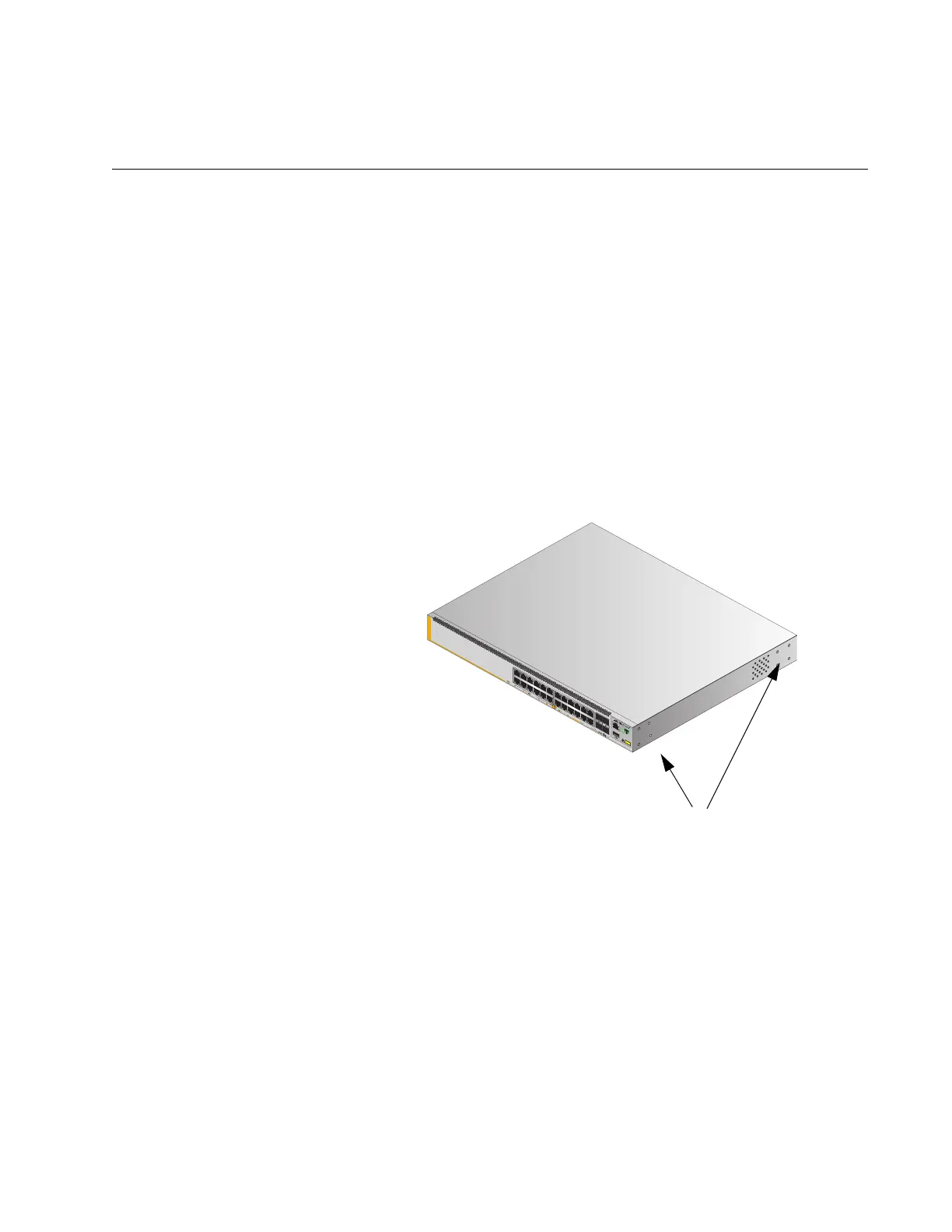
The switch has two sets of four screw holes on the left and right sides, for
attaching the brackets. Refer to Figure 64.
Figure 64. Bracket Holes on the Switch
4581
4568
3
5
1
7
911 13 15
17 19
21
23 27/S1
28/S2
25 SFP+
26
AT-x530L-28GTXm
16 18 20
14
10G/1G
4
6 8 10 122
22
24
FDX
HDX COL
1G LINK
ACT
100 LINK
ACT
5G/2.5G/1G LINK
ACT
100 LINK
ACT
PORTS 21-24
PORTS 1-20
5G/2.5G/1G/100
CLASS
1
LASER PRODUC
T
CONSOLE
Bracket Holes

 Loading...


