Chapter 6: Installing the Switch on a Wall
138
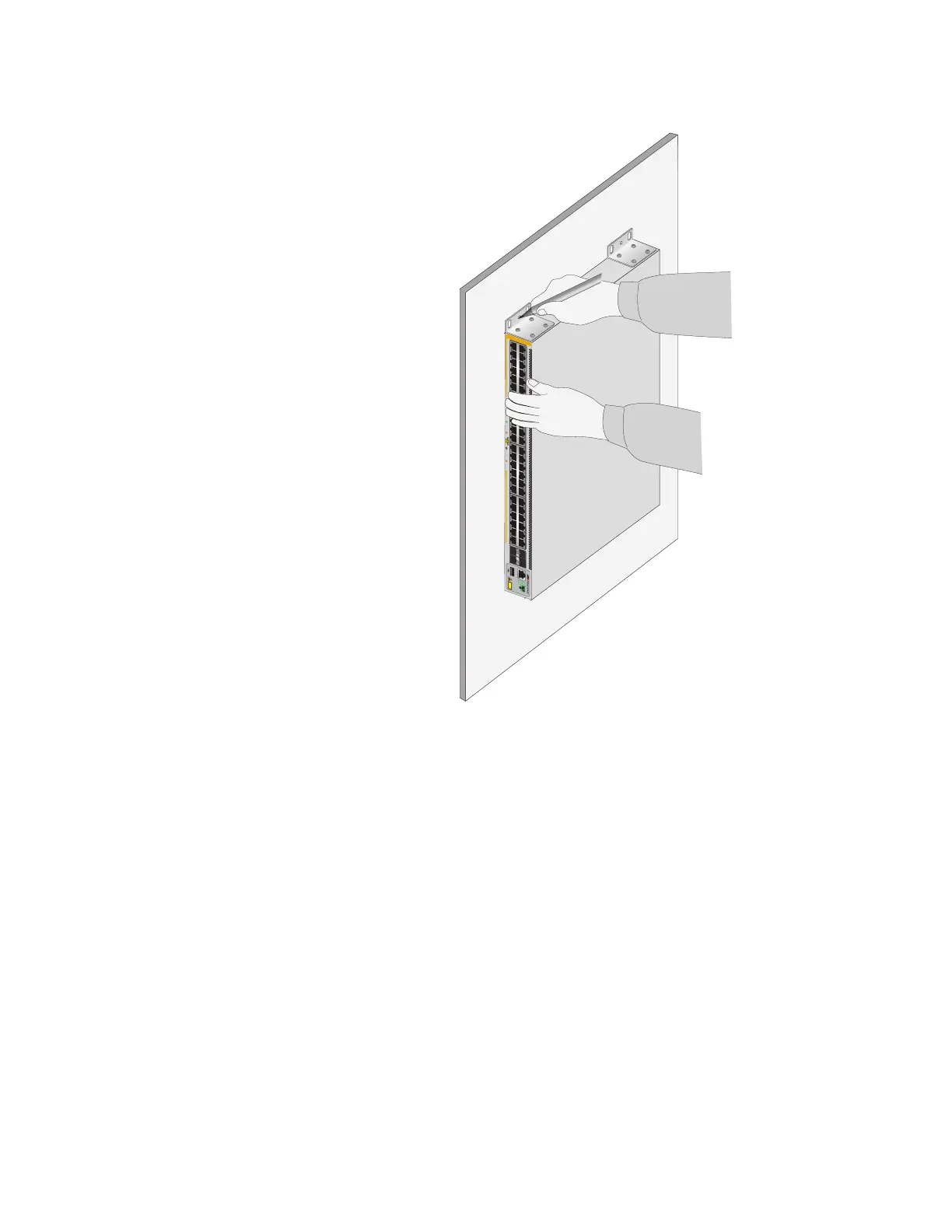
Figure 78. Marking the Locations of the Bracket Holes on a Concrete Wall
4. Place the switch on a table.
5. Use a drill and a 1/4-inch carbide drill bit to pre-drill the holes you
marked in step 3. Please review the following guidelines:
Prior to drilling, set the drill to hammer and rotation mode. The
modes break up the concrete and clean out the hole.
Clean out the holes with a brush or compressed air.
6. Insert the anchors into the holes.
4596
51/S1
52/S2
49
SFP+
50
3
5
1
7
911
13
15
17
19
21
23
4
6
8
10
12
2 16
18
20
14
22
24
27
29
25
31
33
35
37
39
41
43
45
47
28
30
32
34
36
26
40
42
44
38
46
48
10G/
1G
1G LINK
ACT
100 LINK
ACT
PD ON
PD ERR
MAX CURRENT
AT-x530L-52GPX
CONSOLE
CLASS 1
LESER PRODUCT

 Loading...