EasyManuals Logo

Allied Telesis x530L Series User Manual

Allied Telesis x530L Series
228 pages
To Next Page IconTo Next Page
To Previous Page IconTo Previous Page
Page #145 background imageLoading...
Page #145 background image
x530L Series Installation Guide for Virtual Chassis Stacking
145
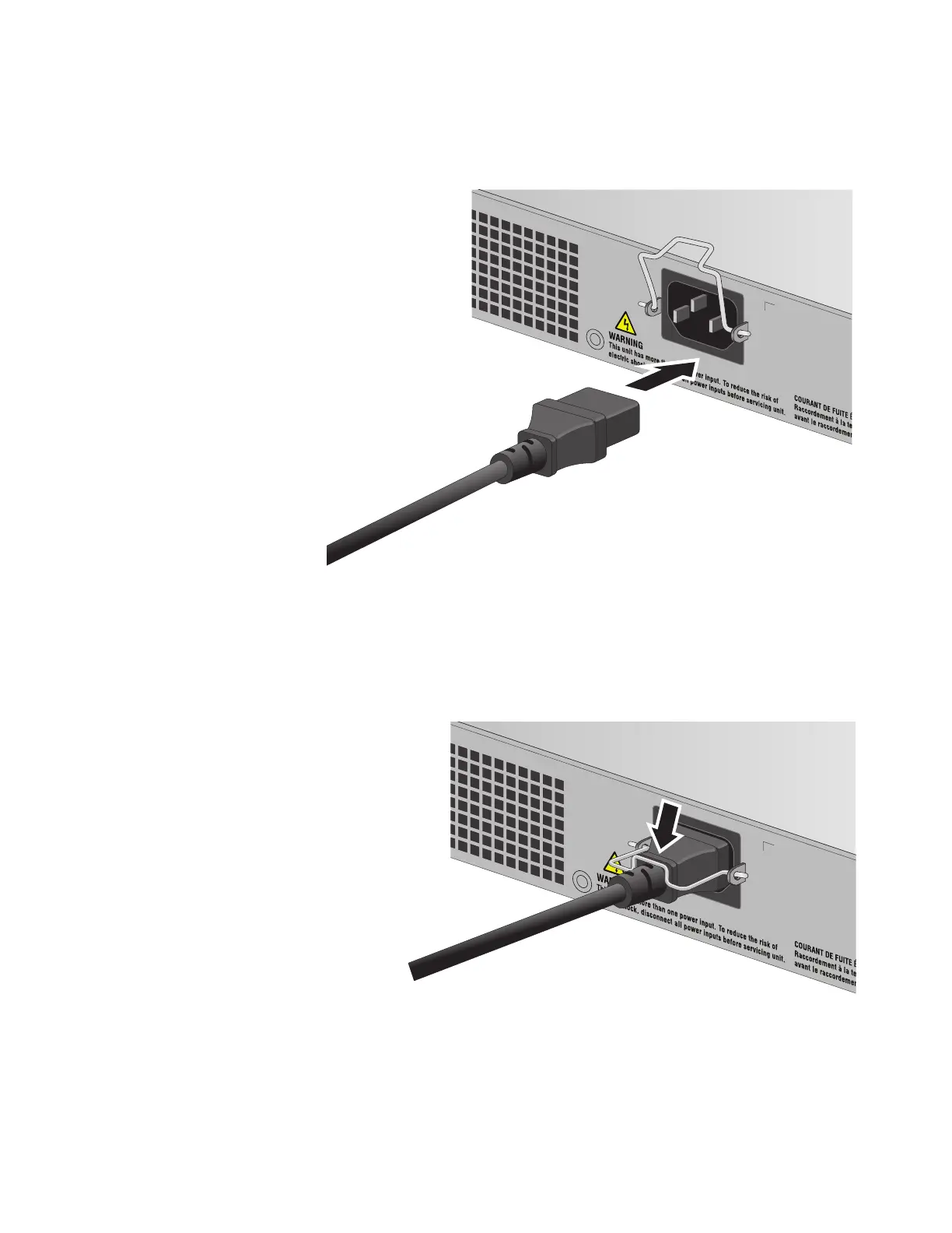
2. Power on the switch you want to be assigned ID number 1 by
connecting its power cord to the AC connector on the back panel.
Refer to Figure 82 on page 145.
Figure 81. Plugging in the AC Power Cord to the Switch
3. Lower the power cord retaining clip to secure the cord to the switch.
Refer to Figure 82.
Figure 82. Lowering the Power Cord Retaining Clip
100-240 VAC~
PSU 2
4589
100-240 VAC~
PSU 2
4590

Table of Contents

Questions and Answers:

Question and Answer IconNeed help?

Do you have a question about the Allied Telesis x530L Series and is the answer not in the manual?

Allied Telesis x530L Series Specifications

General IconGeneral
BrandAllied Telesis
Modelx530L Series
CategorySwitch
LanguageEnglish

Related product manuals