x530L Series Installation Guide for Virtual Chassis Stacking
97
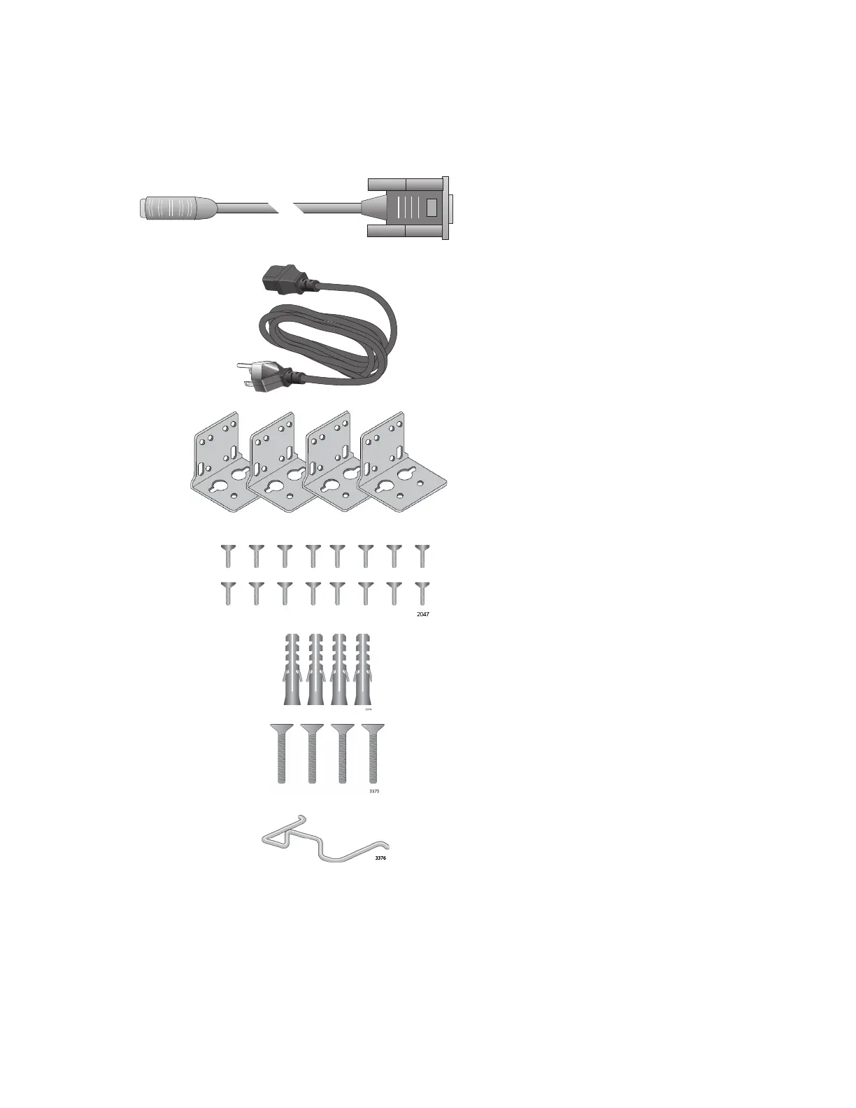
Figure 35 here and Figure 36 on page 98 list the items in the accessory kit.
Contact your Allied Telesis sales representative for assistance if any item
is missing or damaged.
Figure 35. x530L-10GHXm Switch Accessory Kit
One 2m (6.6 ft) local management
cable with RJ-45 (8P8C) and DB-9 (D-
sub 9-pin) connectors.
Sixteen screws for attaching the
BRKT-J24 wall brackets to the
switch.
Length: 6.0mm (0.2 in.)
Diameter: 4.0mm (0.2 in.)
One regional AC power cord
Four anchors for concrete walls:
Length: 29.6mm (1.2 in.)
Diameter: 6.0mm (0.2 in.)
Four screws for wood or concrete
walls:
Length: 32mm (1.3 in.)
Diameter: 4mm (0.2 in.)
Power cord retaining clip
1417
1570
Four BRKT-J24 wall mounting
brackets

 Loading...