Copyright © 1996 General Motors Corp. 7–1
7–1. SCOPE
This section covers assembly of transmission from
subassemblies and parts. Procedures that differ in the
various models, or procedures that apply to only one
model, are identified. Procedures common to all mod-
els have no model identification.
7–2. GENERAL INFORMATION FOR
FINAL ASSEMBLY
Refer to Sections 4 and 8 for assembly information as
follows:
7–3. SELECTIVE COMPONENTS
a. Establish Clearances
(1) Certain components are available in
graduated lengths or thicknesses to provide the proper
running clearances. These components are selected by
taking measurements at certain stages in the assembly
of the transmission.
(2) The components which are selected dur-
ing assembly of the transmission are tabulated below.
Refer to Parts Catalog SA1235 or SA2126 for specific
part numbers.
b. Clutch Plate Stack Measurements
(1) First clutch clearance can be determined
by direct measurement (Paragraph 7–4) or by stack di-
mension measurement (Paragraph 6–7
f
). Refer to
Paragraph 6–17
e
for stack dimension measurement to
establish clutch clearance for second clutch. The clear-
ance for third clutch is established by direct measure-
ment in this section (Paragraph 7–7).
(2) An initial clutch plate running clearance
check may be in excess of the required dimension. Do
not install a thicker backplate if excess clearance can
be eliminated by installing new clutch plates.
7–4. INSTALLATION OF FIRST
CLUTCH AND GEARING
a. First Clutch
(Foldout 10,B)
(1) Place the transmission housing assembly
into the holding fixture, converter housing upward.
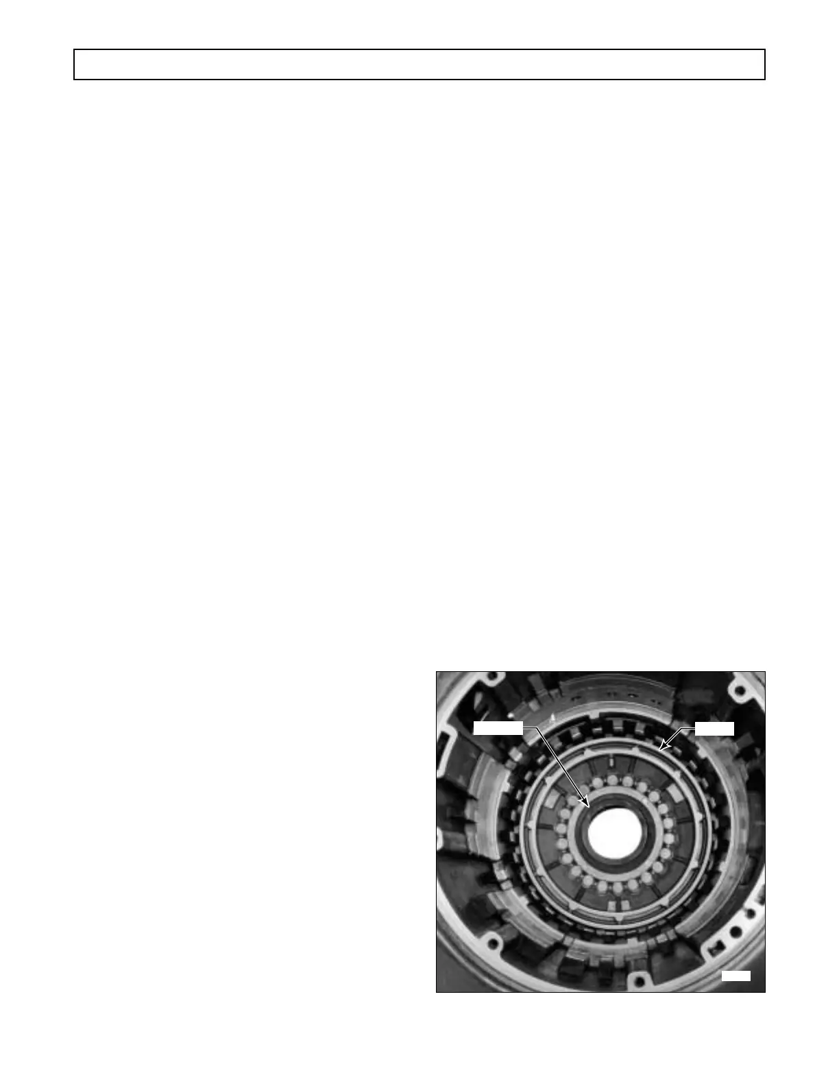
(2) Place inner seal protector tool J 24216-01
over the hub in the transmission housing (Figure 7–1).
(3) Install the inner and outer lip-type seal-
rings into the grooves in the first clutch piston. A
color-coded, outer lip-type sealring (blue) is used on
the piston after S/N 3210201937. The lips of both seal-
rings must face toward the rear of the transmission
when the piston is installed. (Refer to sealring cross-
sections on Foldout 10,B.) Lightly lubricate the sur-
face of the piston bore and protector J 24216-01 with
transmission fluid before installation.
(4) Install the piston and sealrings into the
transmission housing rear bore, engaging the piston
tang into the slot in the housing (Figure 7–1). Be sure
the lip of the sealring on the outside diameter of the
piston is not distorted. Remove the protector tool.
Figure 7–1. Installing First Clutch Piston
Paragraph Description
4–2 Tools and Equipment
4–3 Replacement Parts
4–4 Careful Handling
4–6 Assembly Procedures
4–10 Torque Specifications
8–1 Wear Limits Data
8–2 Spring Data
Component Item Illustration
Thrust washer 37 (Foldout 7,B)
Snapring 5 (Foldout 9,B)
First clutch backplate 2 (Foldout 10,B)
Spacer 3 (Foldout 12,B)
Section 7 – ASSEMBLY OF TRANSMISSION
 Loading...


