7–2 Copyright © 1996 General Motors Corp.
AT 500, 1500 SERIES AUTOMATIC TRANSMISSIONS
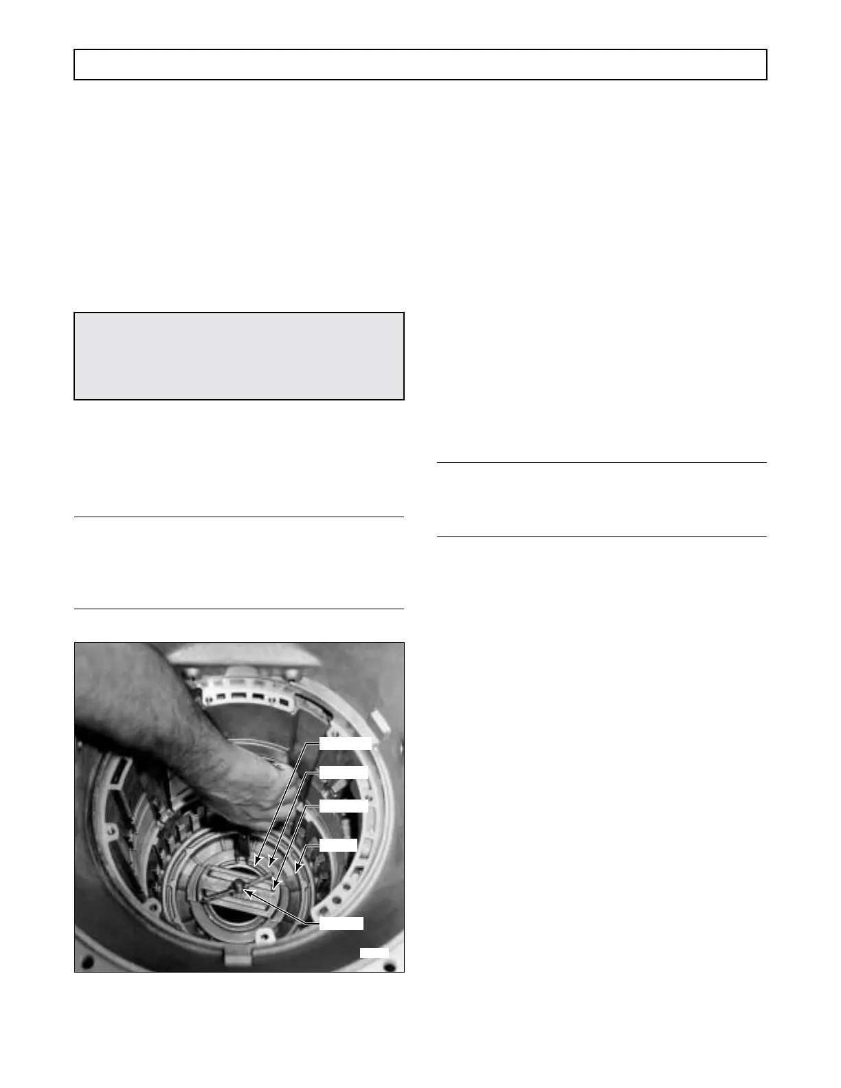
(5) Install twenty-two springs into the re-
cesses in the piston. Install the spring retainer onto the
springs (Figure 7–2).
(6) Lay the spring retainer snapring on the
spring retainer (Figure 7–2).
(7) Install spring compressor assembly
J 23630-02 into the rear bearing bore of the transmis-
sion housing (Figure 7–2). Check the springs for
proper alignment.
(8) Tighten the wing-nut on the spring com-
pressor until the spring retainer clears the snapring
groove in the housing hub. Install the snapring into its
groove. Remove the spring compressor.
NOTE:
For models before S/N 5071, proceed with Step (9).
For models after S/N 5070, skip Steps (9) and (10)
and proceed with Step (11).
Figure 7–2. Installing First Clutch
Spring Retainer Snapring
(9) For models before S/N 5071, install all
fourteen first clutch plates into the transmission as fol-
lows. Beginning with an external-tanged plate, alter-
nately install seven external-tanged plates 4 (Foldout
10,B) and seven internal-splined clutch plates 3.
(10) Install the clutch backplate (wide surface
down) and secure it with a snapring. The first clutch
snapring must be installed with the snapring gap at the
12 o'clock position (at the top of the transmission
housing) and must be fully seated in its groove. Pro-
ceed to Paragraph 7–4
b
and continue rebuild.
(11) After S/N 5070, place ring gear 5 (Fold-
out 10,B) on a work table, extended teeth downward.
Beginning with an internal-splined plate, alternately
install six internal-splined and six external-tanged
clutch plates onto the rear ring gear (Figure 7–3).
NOTE:
Assemble ring gear 5 (Foldout 10,B) with extended
teeth
upward
in housing.
(12) Pick up the ring gear and assembled first
clutch plates. Invert the assembly. Align the tangs of
the external clutch plates on the ring gear and install
the gear and plates into the transmission as a package.
Be sure the extended teeth on the ring gear are at the
top
of the gear after installation.
(13) Install the two remaining clutch plates,
external-tanged plate first. Install the clutch backplate
(Figure 7–4) (wide surface down) and secure it with a
snapring (Figure 7–5). The first clutch backplate
snapring must be installed with the snapring gap at the
12 o'clock position (at the top of the transmission
housing) and must be fully seated in its groove.
b. First Clutch Running Clearance
(Foldout 10,B)
(1) Using clutch clearance gauge J 23715,
check the clearance between the snapring and the back-
plate (Figure 7–5). The smaller end of the gauge should
go into the clearance while the larger end should not.
The running clearance is satisfactory when the dimen-
sion is 0.040–0.100 inch (1.02–2.54 mm).
CAUTION:
When installing the first clutch snapring, do not
allow the spring retainer to catch in the snapring
groove.
H02910
SNAPRING
RETAINER
J 23630-02
J 23630-3
PISTON
 Loading...


