Copyright © 1996 General Motors Corp. 7–13
ASSEMBLY OF TRANSMISSION
NOTE:
• For models with retarder, proceed with Step (8).
• For models without retarder, skip Step (8) and
proceed with Step (9).
(8) For models with retarder, install six M6-1
bolts 39 (Foldout 7,B). Tighten bolts 39 to 9–10 lb ft
(12–14 N
.
m).
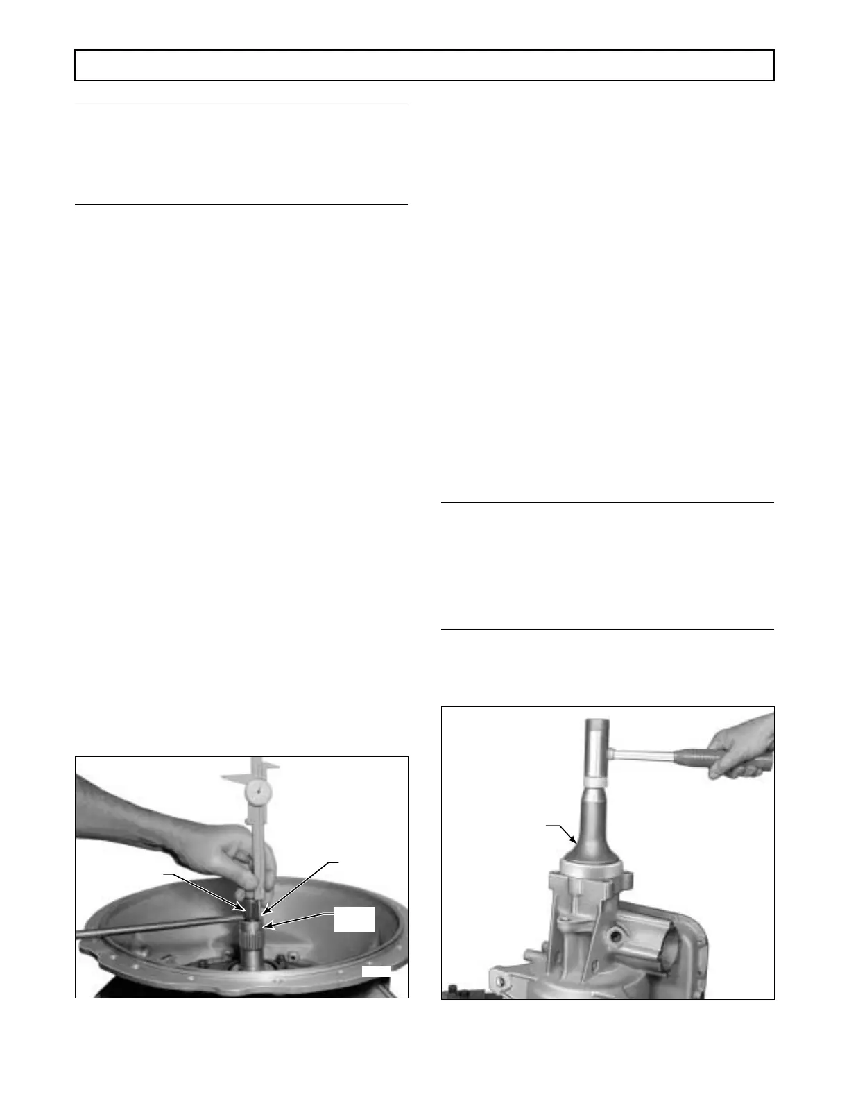
(9) To check the turbine shaft end play,
mount a vernier dial caliper on the turbine shaft. Raise
the shaft, extending the depth gauge to bear upon the
stator shaft and record the dial reading (Figure 7–30).
(10) Release the shaft and record the dial read-
ing. If the dial reading does not fall within the desired
end play range of 0.005–0.034 inch (0.13–0.85 mm),
the thickness of the selective thrust washer must be re-
calculated.
(11) Remove the compressor base, J 23630-2,
installed in Paragraph 7–6a, from the transmission
housing and output shaft.
7–9. INSTALLATION OF OUTPUT
SHAFT OIL SEAL
(Foldout 12,B)
(1) Refer to Paragraph 4–6e. Coat the lip of
oil seal 6 with high temperature grease.
Figure 7–30. Measuring Turbine Shaft End Play
(2) Start the oil seal, lip first, squarely into
the rear bore of the transmission housing.
(3) Using installer tool J 23631, drive the oil
seal into the housing until the installer seats against the
housing (Figure 7–31). The rear of the oil seal will be
0.51–0.55 inch (13.0–14.0 mm) forward of the brake
mounting surface of the transmission housing when
properly installed.
(4) Refer to Paragraph 3–16h for the instal-
lation of the output flange and retaining bolt and
washer.
7–10. INSTALLATION OF MAIN
CONTROL VALVE BODY, OIL
FILTER, AND OIL PAN
a. Main Control Valve Body
NOTE:
If the control valve body assembly was replaced, it
will perform properly only if it is functionally com-
patible with the main housing channeling. Refer to
Parts Catalog SA1235 for part numbers and serial
number application.
(1) Position the transmission housing bottom
side upward.
Figure 7–31. Installing Output Shaft Oil Seal
H02997
STATOR
SHAFT
DEPTH
GAUGE
TURBINE SHAFT
 Loading...


