7–12 Copyright © 1996 General Motors Corp.
AT 500, 1500 SERIES AUTOMATIC TRANSMISSIONS
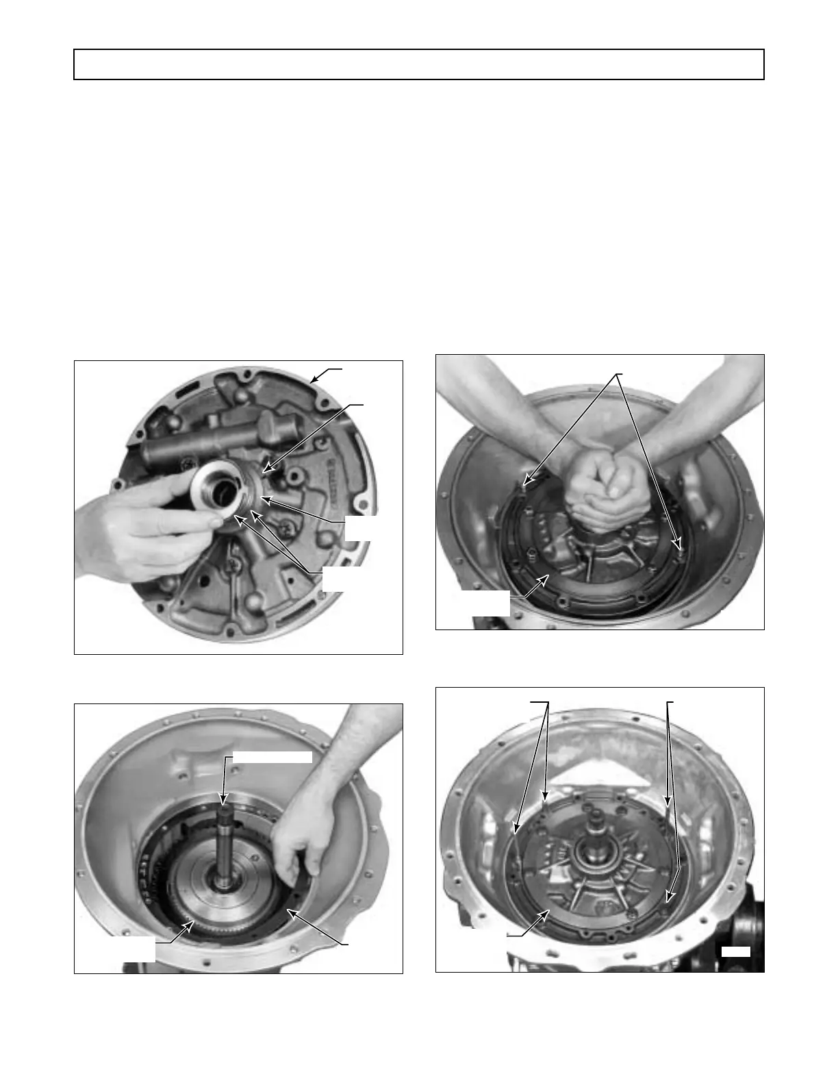
b. Pump Assembly (Foldout 7,B)
(1) Using oil-soluble grease, install the thrust
washer selected in Paragraph 7–8a(3), onto the oil
pump assembly (Figure 7–26). The tab on the washer
must engage the cast recess in the front support.
(2) Install two hook-type sealrings onto the
hub of the front support (Figure 7–26).
(3) Lubricate the sealrings and thrust washer
with oil-soluble grease.
(4) Install the front support gasket, aligning
the bolt holes in the gasket with those in the transmis-
sion housing (Figure 7–24 or 7–27).
Figure 7–26. Installing Hook-Type
Sealrings Onto Oil Pump Assembly
Figure 7–27. Installing Front Support Gasket
(Models Without Retarder)
(5) Install two
5
⁄16-18 headless guide bolts
into two opposite holes in the gasket and transmission
housing (Figure 7–24 or 7–28).
(6) Grasp the oil pump assembly by the sta-
tor shaft and lower it into the transmission housing
(Figure 7–28 or 7–29). Be sure the support bottoms.
Remove the guide bolts.
(7) Install nine
5
⁄16-18 x 1
3
⁄4 inch self-lock-
ing bolts, with nine new rubber coated washers, into
the front support and transmission housing. Tighten
the bolts to 13–16 lb ft (17–22 N
.
m).
Figure 7–28. Installing Oil Pump Assembly
(Models Without Retarder)
Figure 7–29. Installing Oil Pump Assembly
(Models With Retarder)
H02994
TAB
PUMP
ASSEMBLY
HOOK-TYPE
SEALRING (2)
THRUST
WASHER
H02995
TURBINE SHAFT
GASKET
FORWARD
CLUTCH
H02996
GUIDE PINS
OIL PUMP
ASSEMBLY
H03021
GUIDE BOLTS GUIDE BOLTS
OIL PUMP
ASSEMBLY
 Loading...


