Copyright © 1996 General Motors Corp. 7–11
ASSEMBLY OF TRANSMISSION
7–8. INSTALLATION OF
OIL PUMP ASSEMBLY
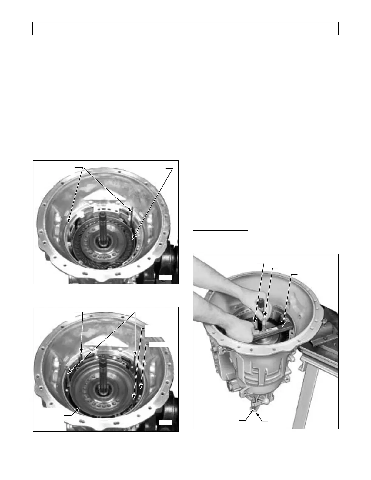
a. Selection of Front Thrust Washer
(Foldout 7,B)
(1) Lay thrust washer selection gauge bar
J 23633 in the transmission housing (Figure 7–25).
Place the depth micrometer so that its stem passes
through the center hole in the gauge bar.
(2) Align the gauge bar so that the microme-
ter stem is above the thrust washer surface of the for-
ward clutch housing (Figure 7–25).
Figure 7–23. Installing Retarder Housing Assembly
Guide Pins (Models With Retarder)
Figure 7–24. Installing Retarder Front Stator
(Models With Retarder)
(3) Measure the distance from the top of the
gauge bar to the thrust surface of the clutch housing
(Figure 7–25). Subtract 1.00 inch (25.4 mm) or the
thickness of the gauge bar and record the difference.
Select the proper thrust washer from the following ta-
ble.
*Dimension in inches (millimeters)
Figure 7–25. Measuring For Selection
of Front Thrust Washer
H03019
GUIDE BOLTS (2)
M 6-1 x 80 mm
RETARDER
HOUSING
ASSEMBLY
H03020
GUIDE BOLT
5
⁄16-18 x 3 in.
GUIDE BOLT
5
⁄16-18 x 3 in.
GASKET
GUIDE BOLT (2)
M 6-1 x 80 mm
RETARDER
FRONT
STATOR
Dimension* Thrust Washer
NumberFrom To Marked
0.732 0.749 6831620 0
(18.61) (19.03) Black
0.749 0.765 6831621 1
(19.03) (19.44) Red
0.765 0.782 6831622 2
(19.44) (19.86) Blue
0.782 0.798 6831623 3
(19.86) (20.27) Green
0.798 0.814 6831624 4
(20.27) (20.69) Black
0.814 0.831 6831625 5
(20.69) (21.11) Black
H02993
DEPTH MICROMETER
FORWARD CLUTCH
ASSEMBLY
J 23633
J 23630-2
BOLT (2),
1
⁄2-13
 Loading...


