7–10 Copyright © 1996 General Motors Corp.
AT 500, 1500 SERIES AUTOMATIC TRANSMISSIONS
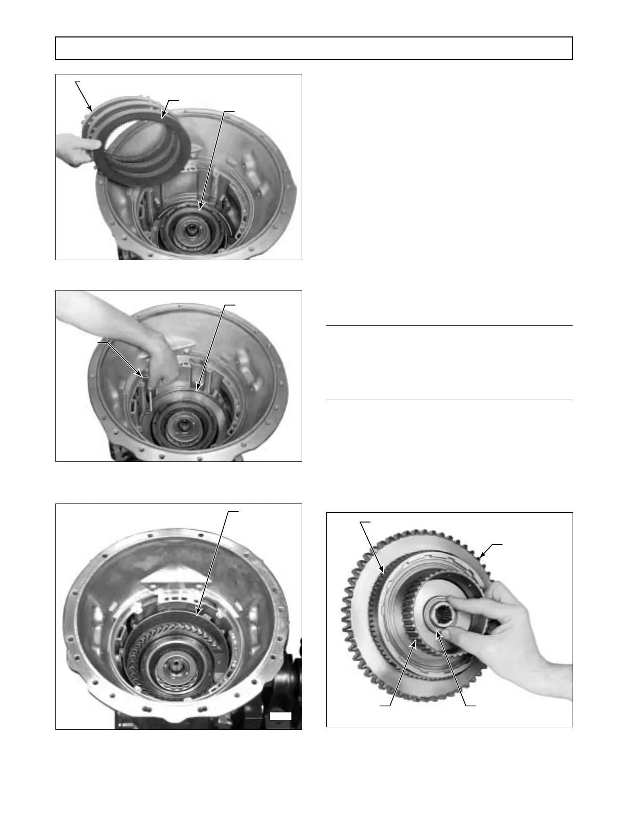
Figure 7–19. Installing Third Clutch Plates
Figure 7–20. Checking Third Clutch Running Clearance
(Models Without Retarder)
Figure 7–21. Installing Retarder Housing Assembly
(Models With Retarder)
c. Forward Clutch and Turbine Shaft
Assembly
(Foldout 8)
(1) Install the thrust washer onto the hub of
the forward clutch assembly, retaining it with oil-solu-
ble grease (Figure 7–22).
(2) Install forward clutch and turbine shaft
assembly. The hub splines engage the transmission
main shaft. The splines on the fourth clutch drive hub
engage the internal splined plates of the fourth clutch.
(3) Rotate the forward clutch assembly one
or two revolutions, while pushing it downward. Make
sure all the fourth clutch internal-splined plates are en-
gaged.
NOTE:
•
For models with retarder, proceed with Step (4).
•
For models without retarder, skip Step (4) and
proceed with Paragraph 7–8.
(4) For models with retarder, install two
M6-1 x 80 mm guide bolts into the retarder housing
assembly (Figure 7–23). Install the front stator, stator
blades first, aligning the holes in the stator with the
holes in the retarder housing assembly (Figure 7–24).
Figure 7–22. Installing Thrust Washer at Rear
of Forward Clutch Hub
H02990
FOURTH CLUTCH
INTERNAL-SPLINED PLATE (3)
EXTERNAL-TANGED PLATE (3) – MODELS WITHOUT RETARDER
(4) – MODELS WITH RETARDER
H02991
SNAPRING
J 23716
H03018
RETARDER
HOUSING
ASSEMBLY
H02992
THRUST WASHER
FOURTH
CLUTCH
DRIVE HUB
FORWARD CLUTCH ASSEMBLY
PTO DRIVE
GEAR
 Loading...


